


step 1:
Download Code from GitHub
git clone https://github.com/aws-samples/aws-three-tier-web-architecture-workshop.git
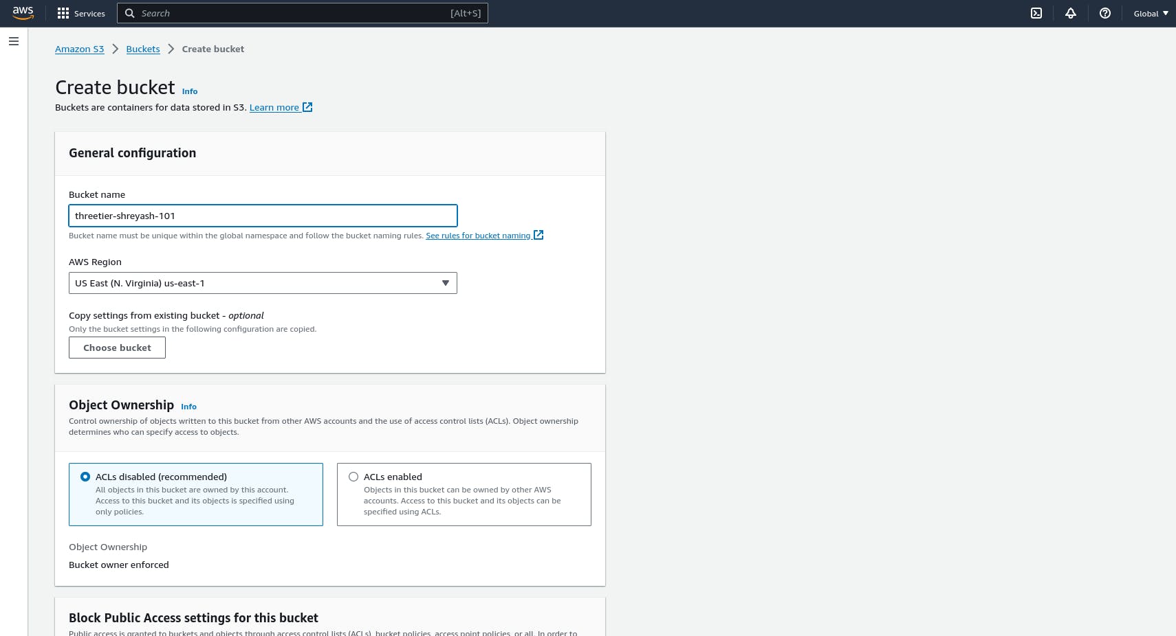
step 2: S3 Bucket Creation
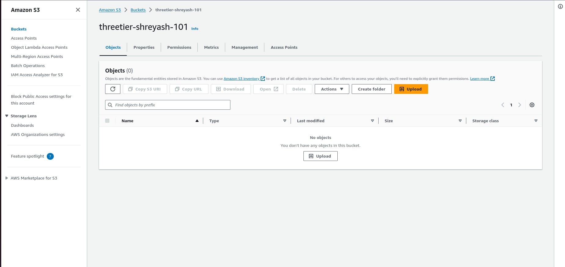
- Navigate to the S3 service in the AWS console and create a new S3 bucket.

2.Give it a unique name, and then leave all the defaults as in. Make sure to select the region that you intend to run this whole lab in. This bucket is where we will upload our code later.
Step 3: IAM EC2 Instance Role Creation
Navigate to the IAM dashboard in the AWS console and create an EC2 role.
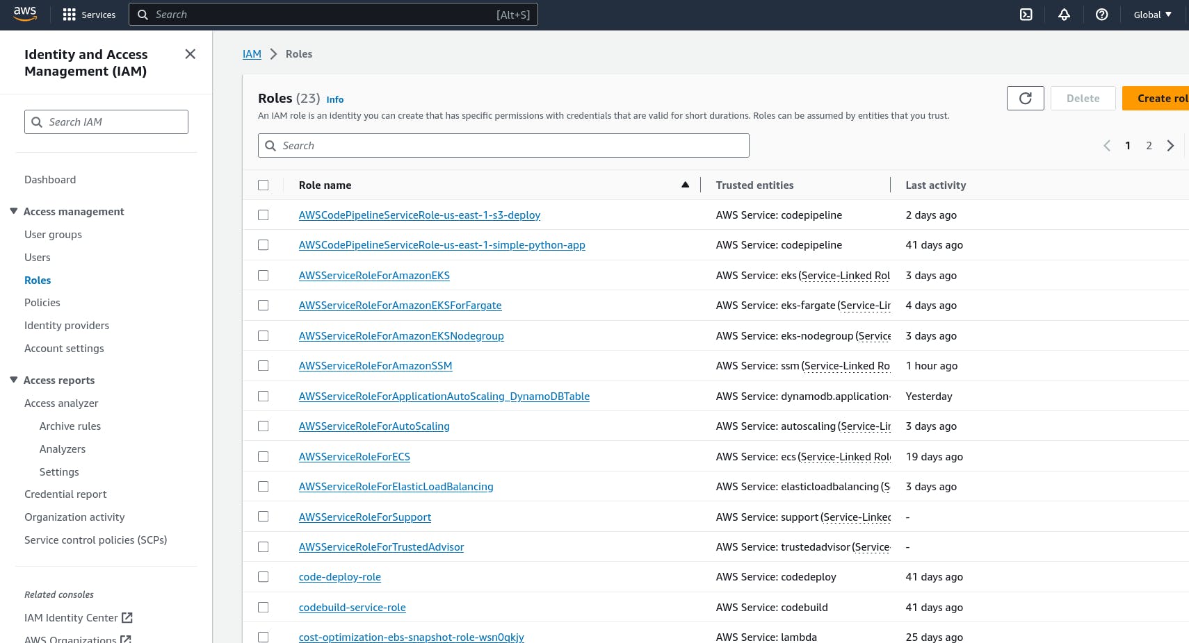
select ec2 as a trusted entity

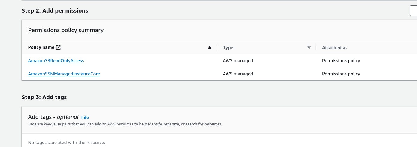
3. When adding permissions, include the following AWS managed policies. You can search for them and select them. These policies will allow our instances to download our code from S3 and use Systems Manager Session Manager to securely connect to our instances without SSH keys through the AWS console.
AmazonSSMManagedInstanceCore
AmazonS3ReadOnlyAccess
Step 4: VPC and Subnets
VPC Creation
- Navigate to the VPC dashboard in the AWS console and navigate to Your VPCs on the left hand side.
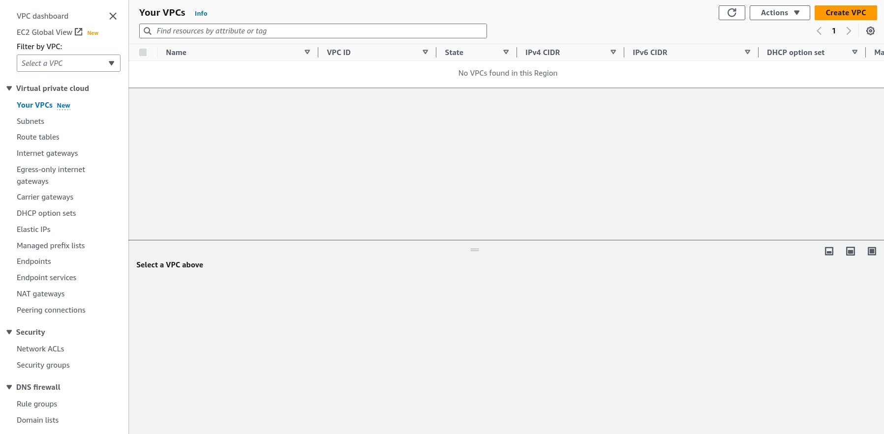
Make sure VPC only is selected, and fill out the VPC Settings with a Name tag and a CIDR range of your choice.
NOTE: Make sure you pay attention to the region you’re deploying all your resources in. You’ll want to stay consistent for this workshop.
NOTE: Choose a CIDR range that will allow you to create at least 6 subnets.
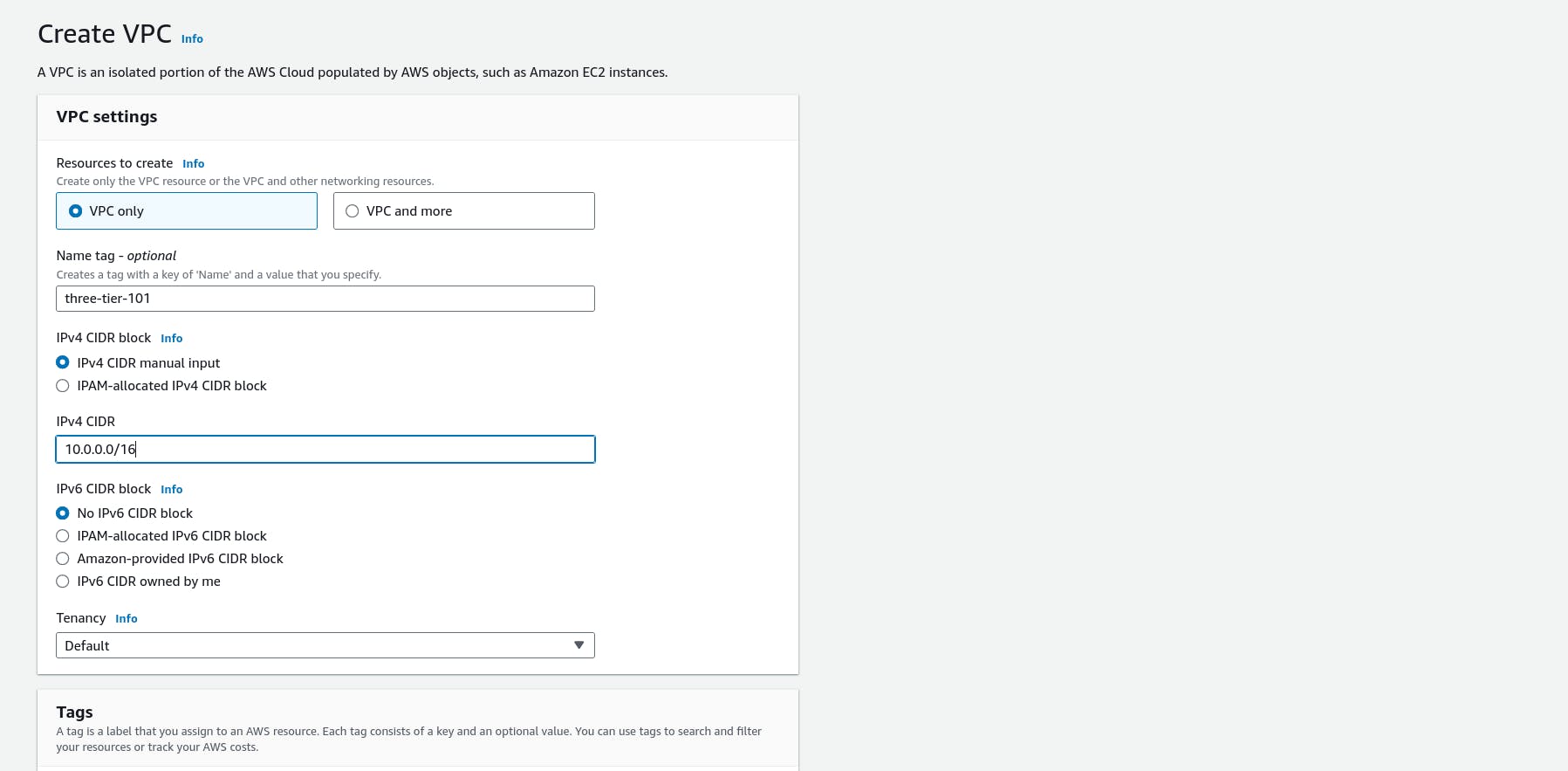
Step 5: Subnet Creation
- Next, create your subnets by navigating to Subnets on the left side of the dashboard and clicking Create subnet.

We will need six subnets across two availability zones. That means that three subnets will be in one availability zone, and three subnets will be in another zone. Each subnet in one availability zone will correspond to one layer of our three tier architecture. Create each of the 6 subnets by specifying the VPC we created in part 1 and then choose a name, availability zone, and appropriate CIDR range for each of the subnets.
NOTE: It may be helpful to have a naming convention that will help you remember what each subnet is for. For example in one AZ you might have the following: Public-Web-Subnet-AZ-1, Private-App-Subnet-AZ-1, Private-DB-Subnet-AZ-1.
NOTE: Remember, your CIDR range for the subnets will be subsets of your VPC CIDR range.
Your final subnet setup should be similar to this. Verify that you have 3 subnets across 2 different availability zones.

Step 6: Internet Connectivity
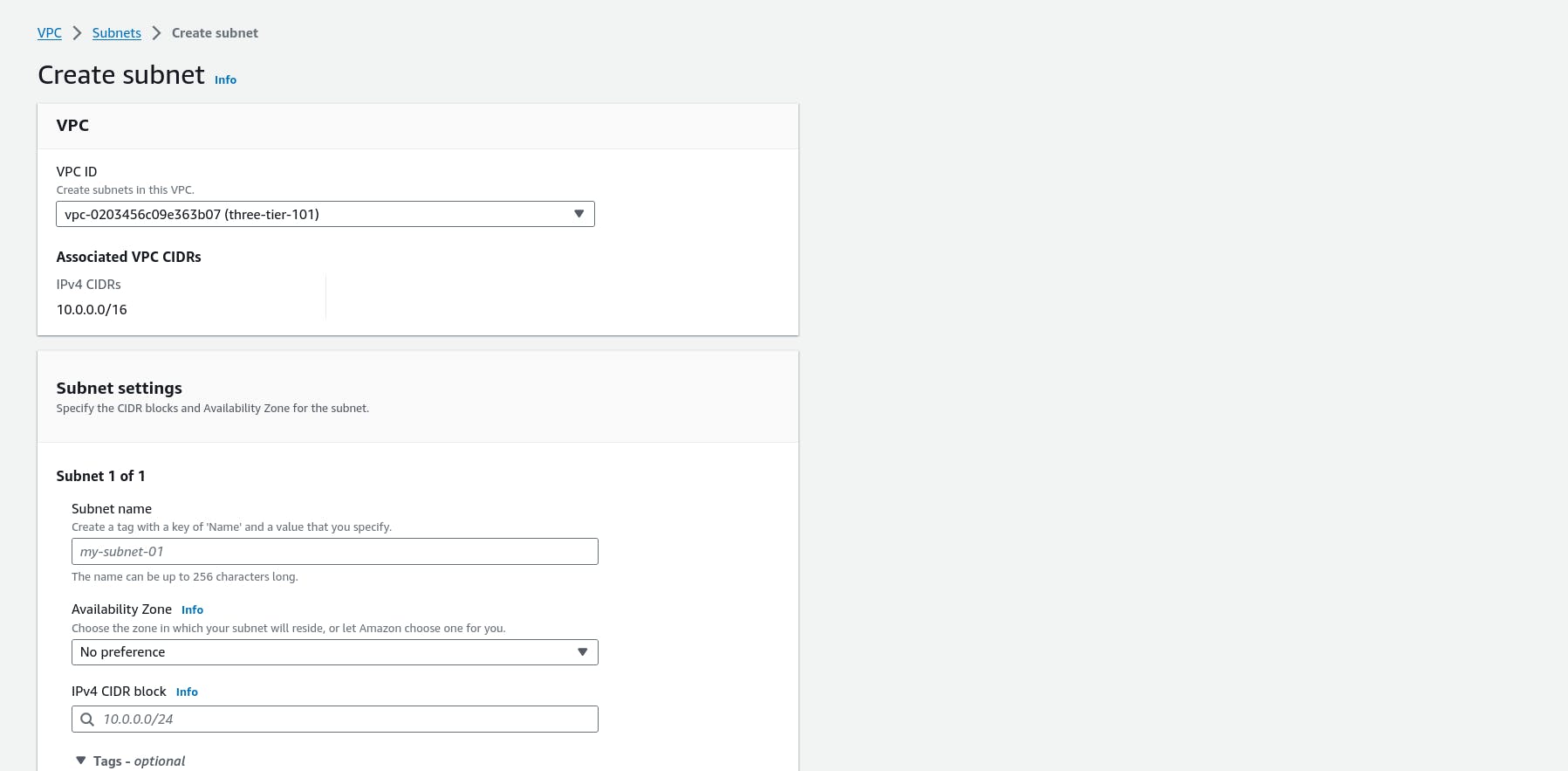
Internet Gateway
- In order to give the public subnets in our VPC internet access we will have to create and attach an Internet Gateway. On the left hand side of the VPC dashboard, select Internet Gateway.
- Create your internet gateway by simply giving it a name and clicking Create internet gateway.

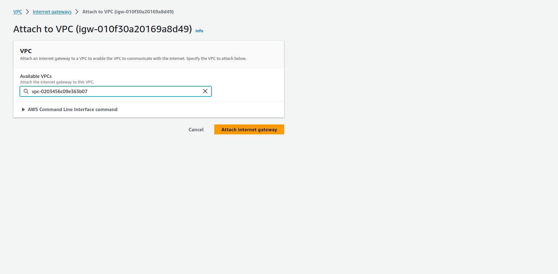
- After creating internet gateway attach it to the vpc that you created in the vpc and subnet creation step of the workshop.
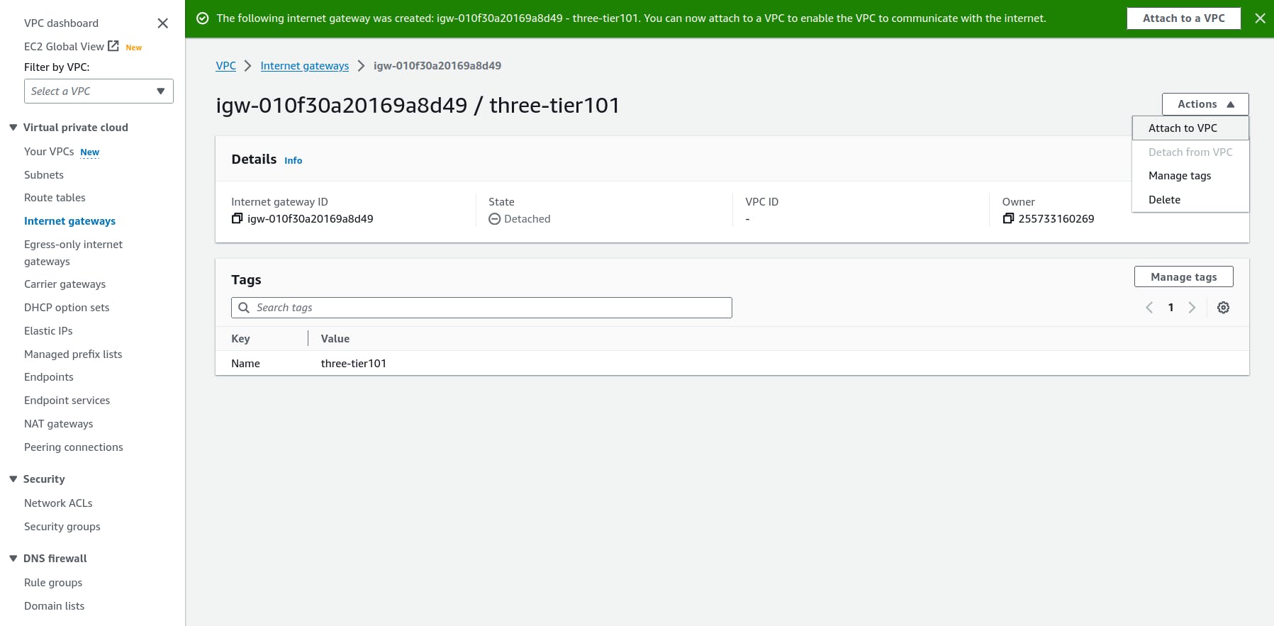
Then select the correct vpc and click attach internet gateway
NAT Gateway
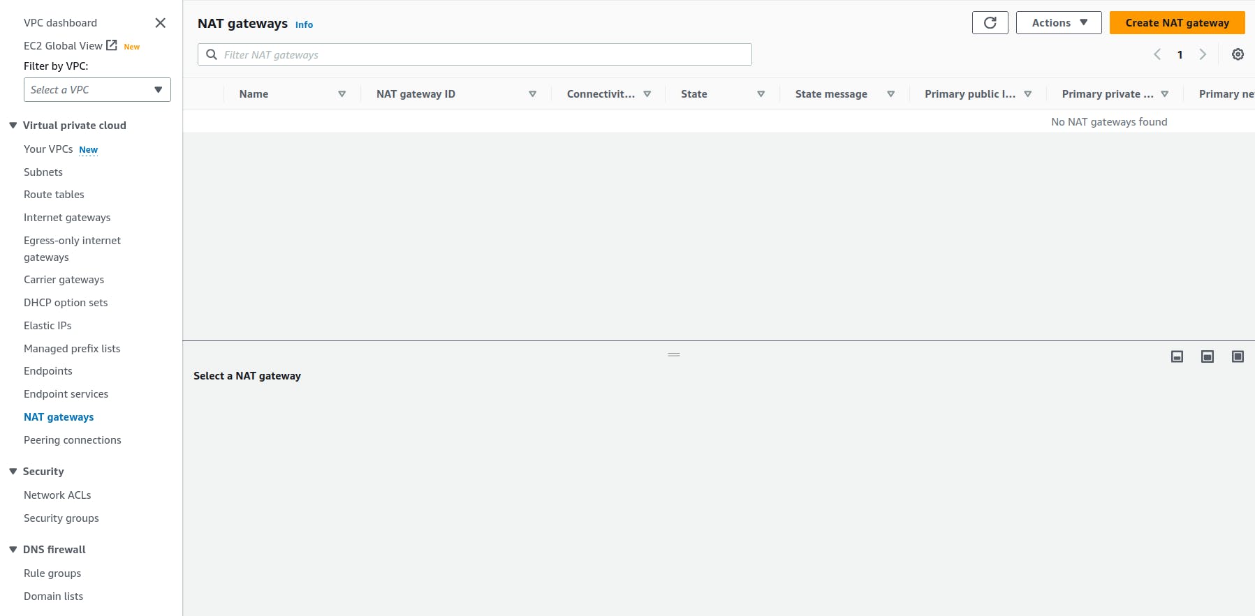
- In order for our instances in the app layer private subnet to be able to access the internet they will need to go through a NAT Gateway. For high availability, you’ll deploy one NAT gateway in each of your public subnets. Navigate to NAT Gateways on the left side of the current dashboard and click Create NAT Gateway.
Fill the name and choose on of the public subnet that you created and then allocate an elastic ip and click on create nat gateway
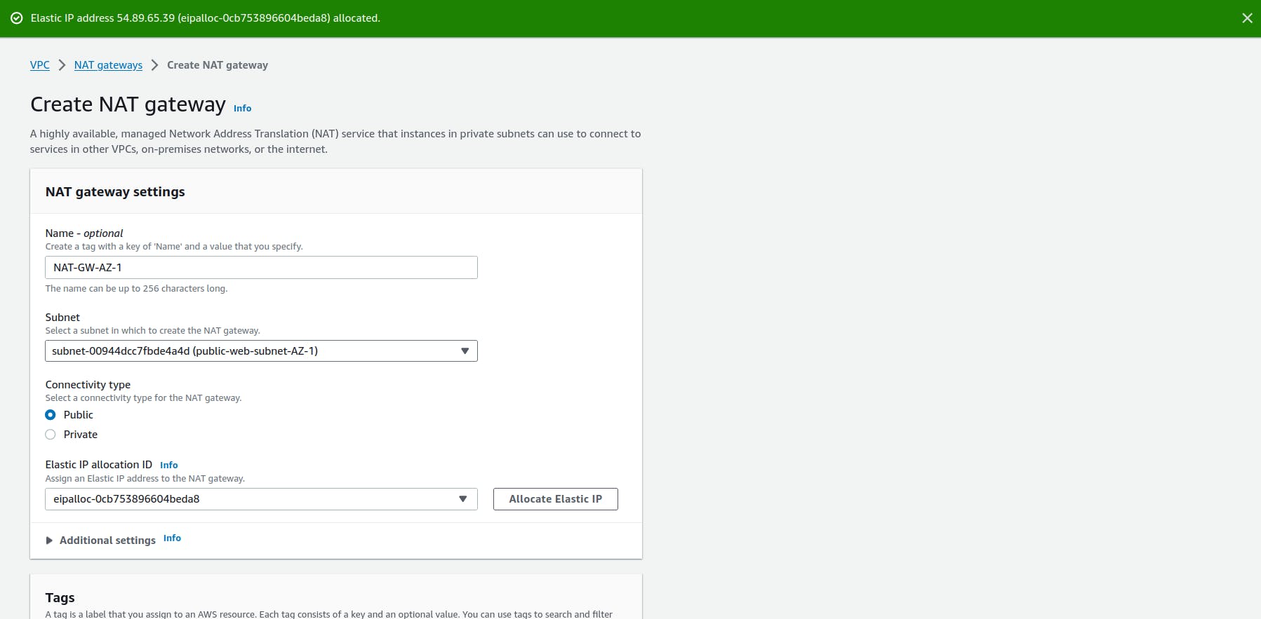
Repeat the step 1 and 2 for the other subnet
Routing Configuration
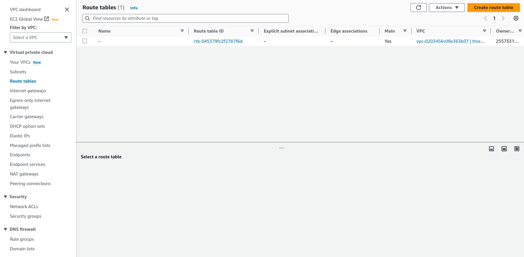
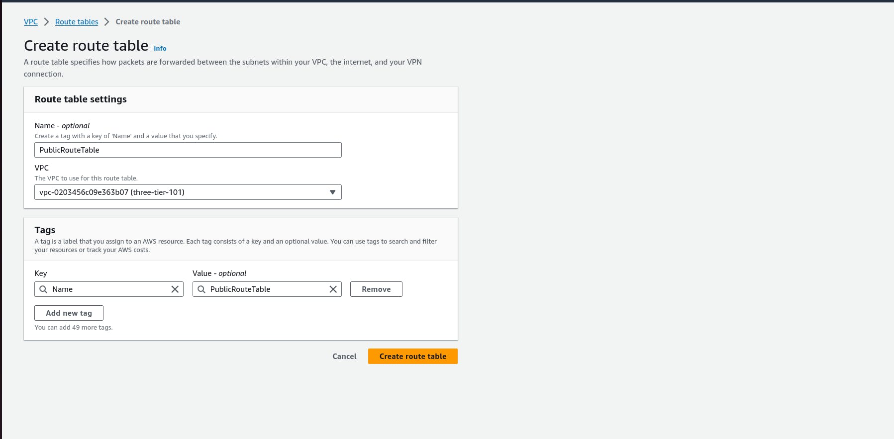
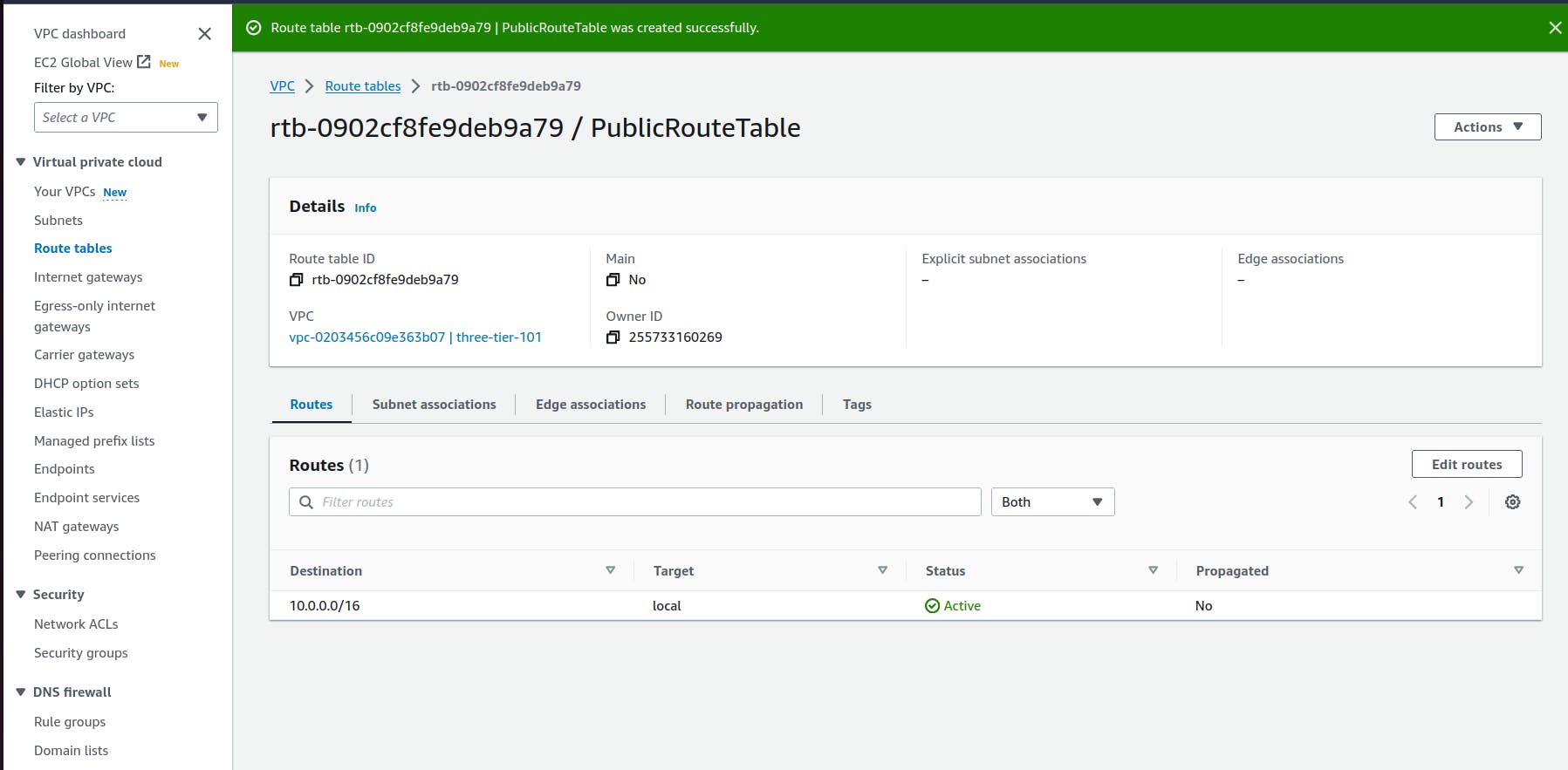
- Navigate to Route Tables on the left side of the VPC dashboard and click Create route table First, let’s create one route table for the web layer public subnets and name it accordingly.
Scroll down and click on the Routes tabEdit routes
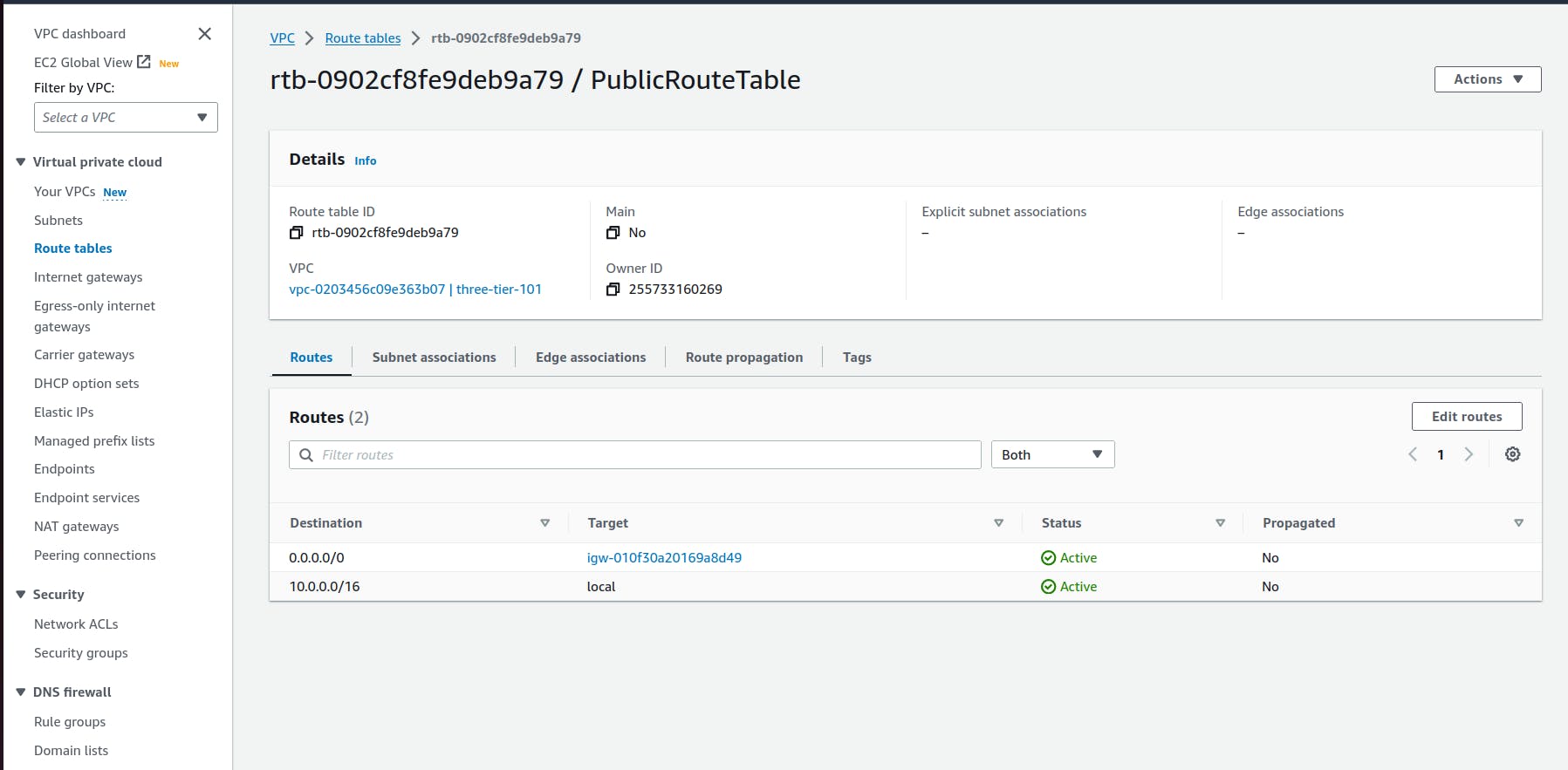
Add a route table that directs traffics from vpc to the internet gateway
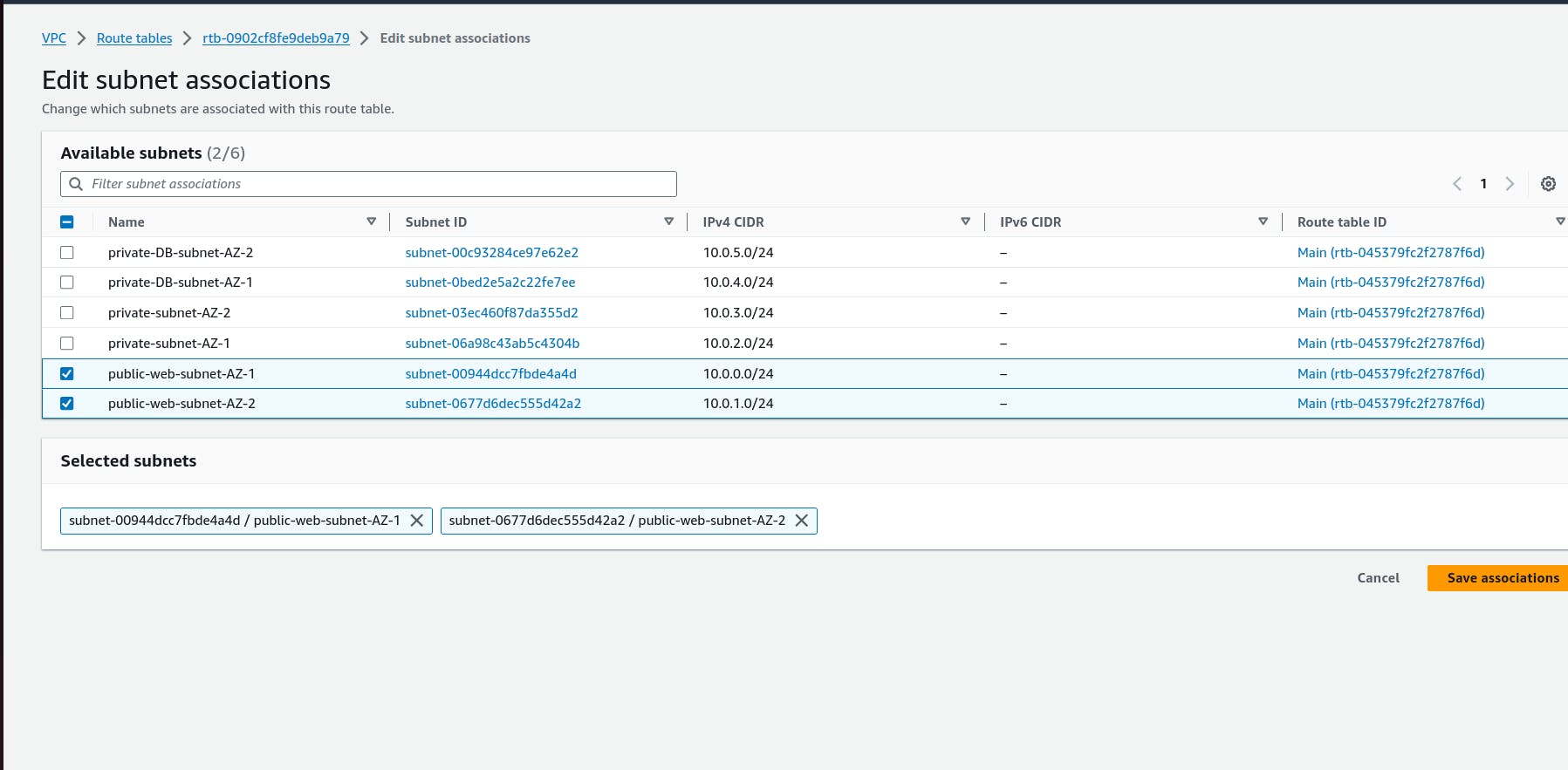
Select Subnet Associations and click Edit subnet associations
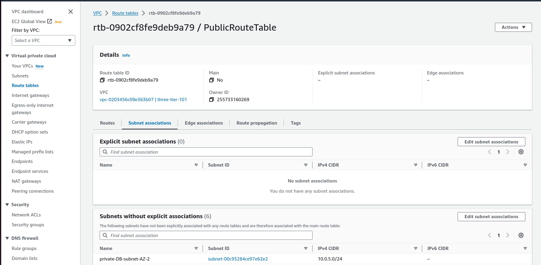
select the two web layer public subnet that you created earlier
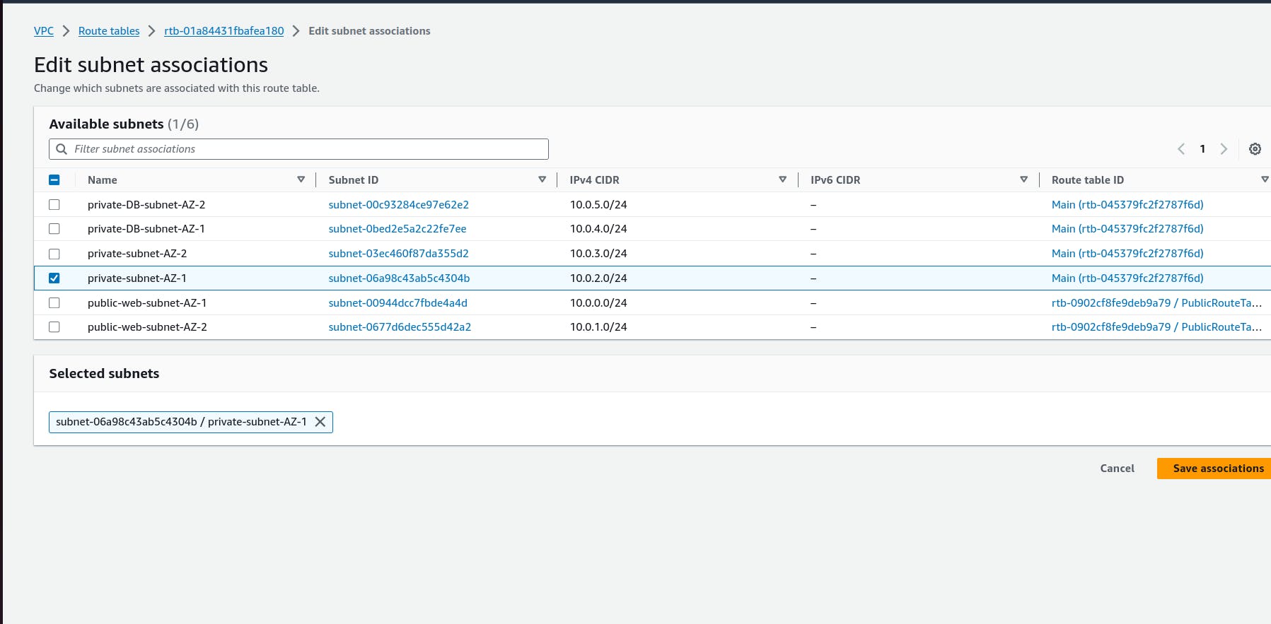
- Now create 2 more route tables, one for each app layer private subnet in each availability zone. These route tables will route app layer traffic destined for outside the VPC to the NAT gateway in the respective availability zone, so add the appropriate routes for that.

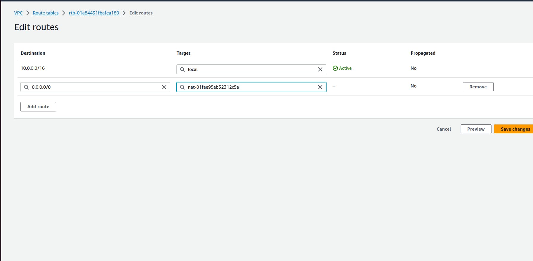
Onces the roures table created and routes added , add the appropriate subnet association for each of the app layer private subnet
step 7: Security Groups
- Security groups will tighten the rules around which traffic will be allowed to our Elastic Load Balancers and EC2 instances. Navigate to Security Groups on the left side of the VPC dashboard, under Security.

- The first security group you’ll create is for the public, internet facing load balancer. After typing a name and description, add an inbound rule to allow HTTP type traffic for your IP.

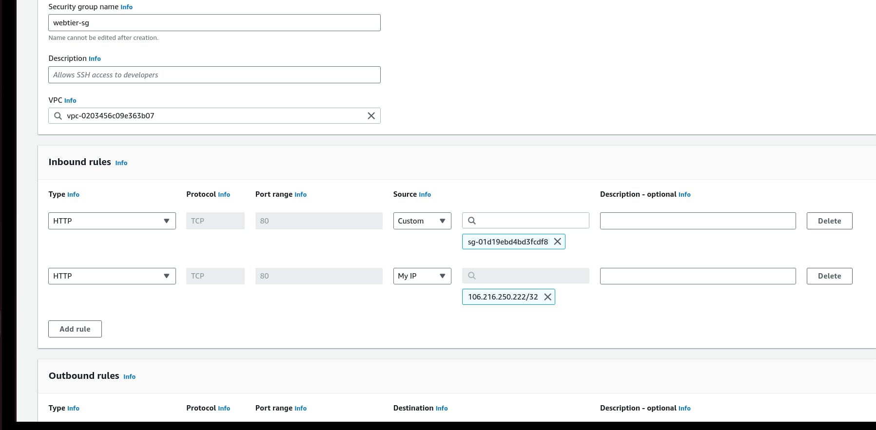
- The second security group you’ll create is for the public instances in the web tier. After typing a name and description, add an inbound rule that allows HTTP type traffic from your internet facing load balancer security group you created in the previous step. This will allow traffic from your public facing load balancer to hit your instances. Then, add an additional rule that will allow HTTP type traffic for your IP. This will allow you to access your instance when we test.
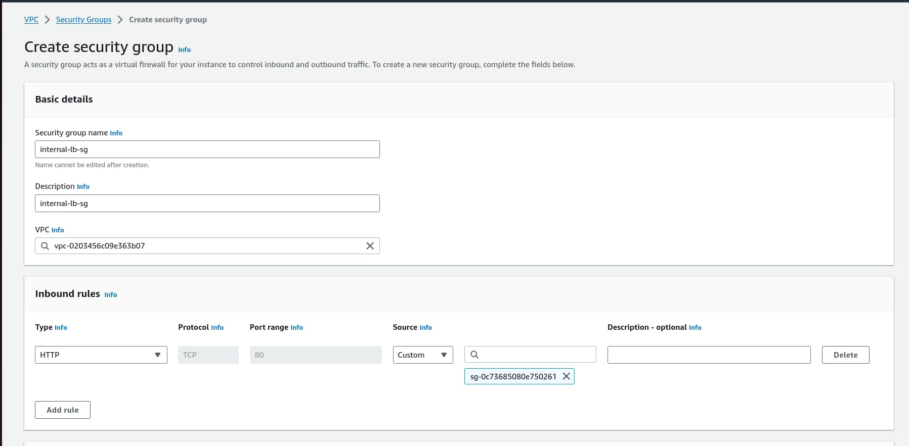
- The third security group will be for our internal load balancer. Create this new security group and add an inbound rule that allows HTTP type traffic from your public instance security group. This will allow traffic from your web tier instances to hit your internal load balancer.
- The fourth security group we’ll configure is for our private instances. After typing a name and description, add an inbound rule that will allow TCP type traffic on port 4000 from the internal load balancer security group you created in the previous step. This is the port our app tier application is running on and allows our internal load balancer to forward traffic on this port to our private instances. You should also add another route for port 4000 that allows your IP for testing.

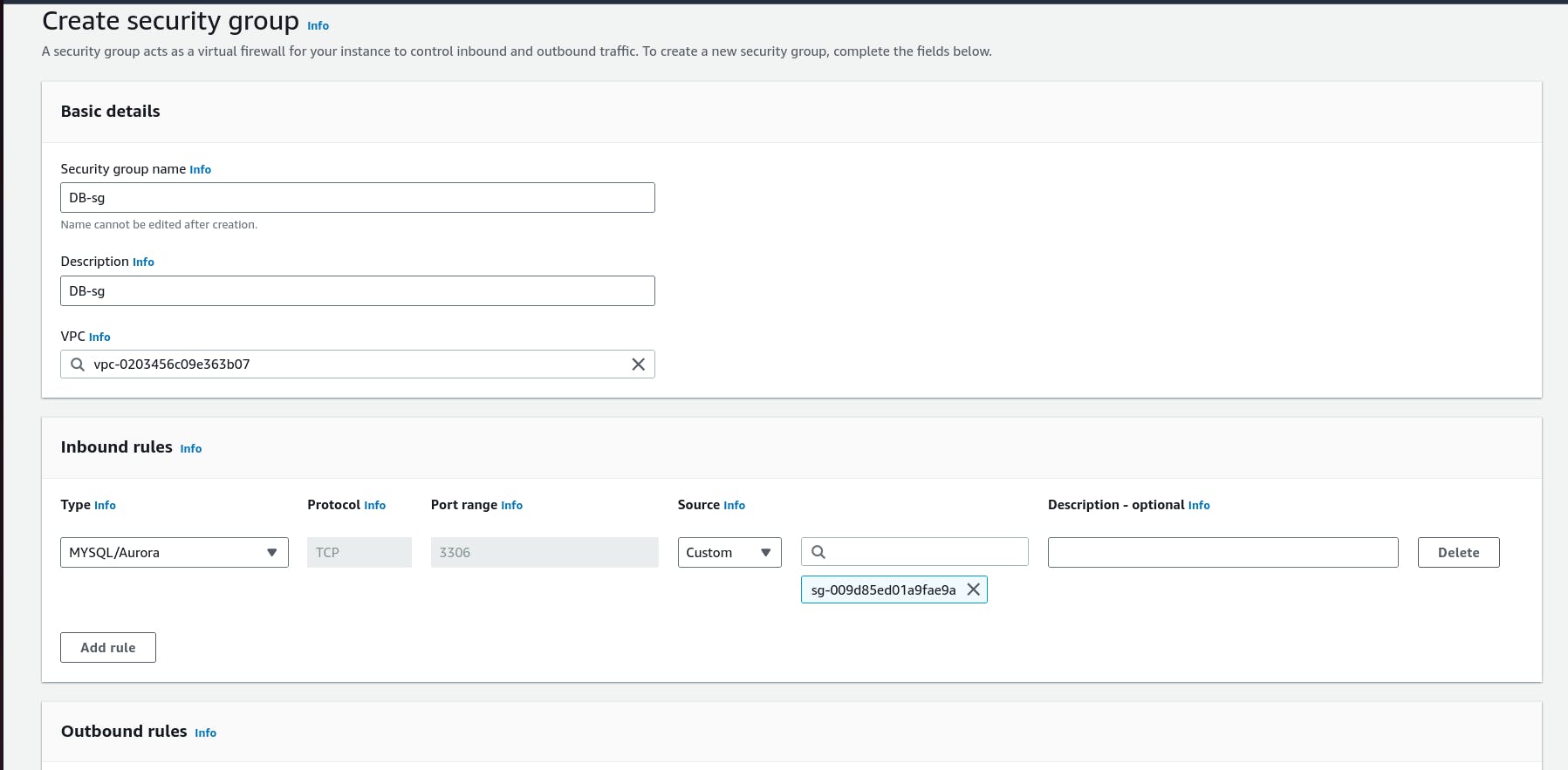
- The fifth security group we’ll configure protects our private database instances. For this security group, add an inbound rule that will allow traffic from the private instance security group to the MYSQL/Aurora port (3306).
Step 8:
Subnet Groups
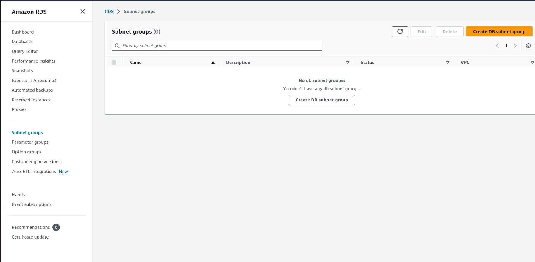
- Navigate to the RDS dashboard in the AWS console and click on Subnet groups on the left hand side. Click Create DB subnet group.
Give your subnet group a name, description, and choose the VPC we created.
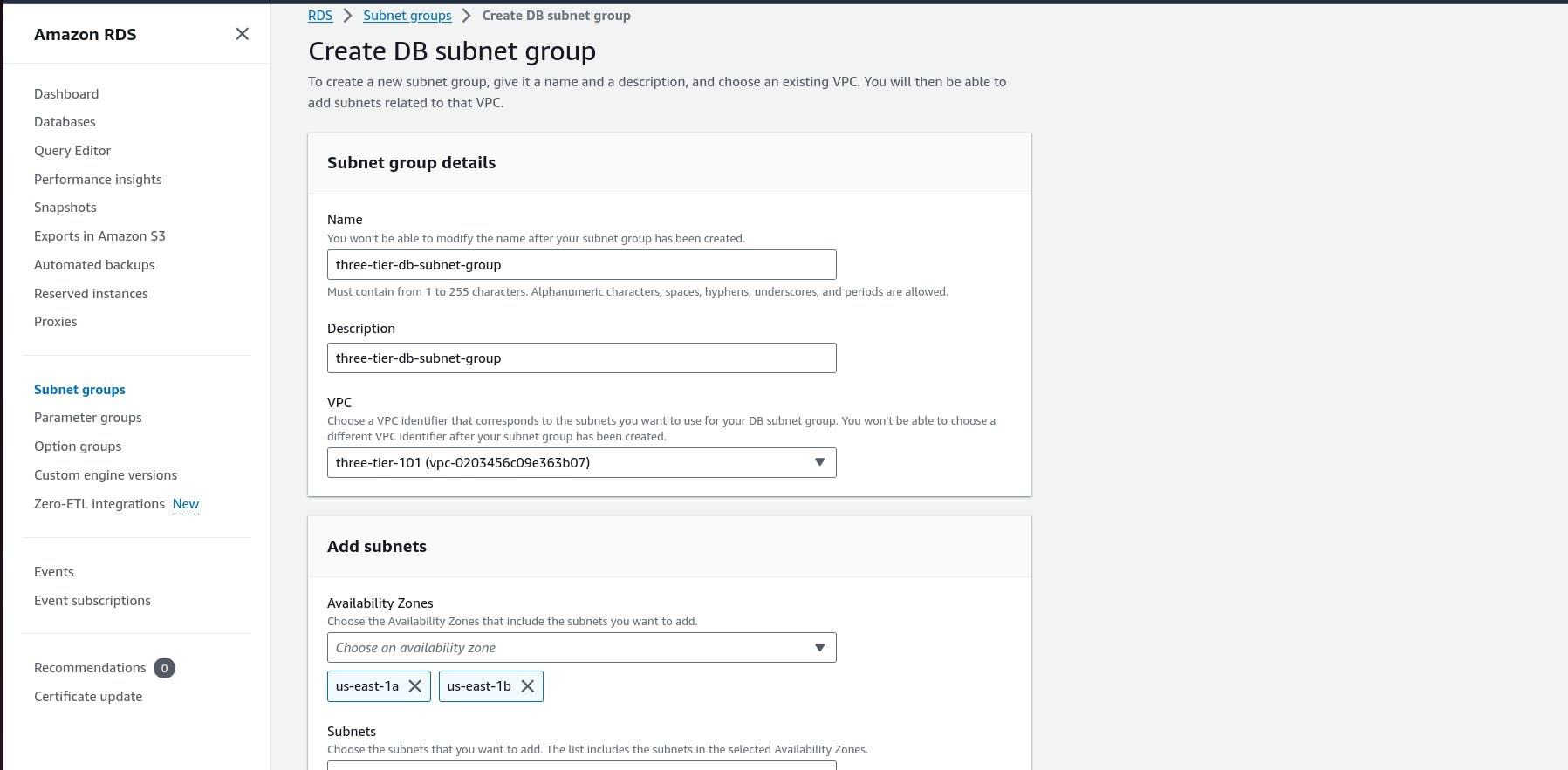
- When adding subnets, make sure to add the subnets we created in each availability zone specificaly for our database layer. You may have to navigate back to the VPC dashboard and check to make sure you're selecting the correct subnet IDs.
Step 9:
Database Deployment
- Navigate to Databases on the left hand side of the RDS dashboard and click Create database.

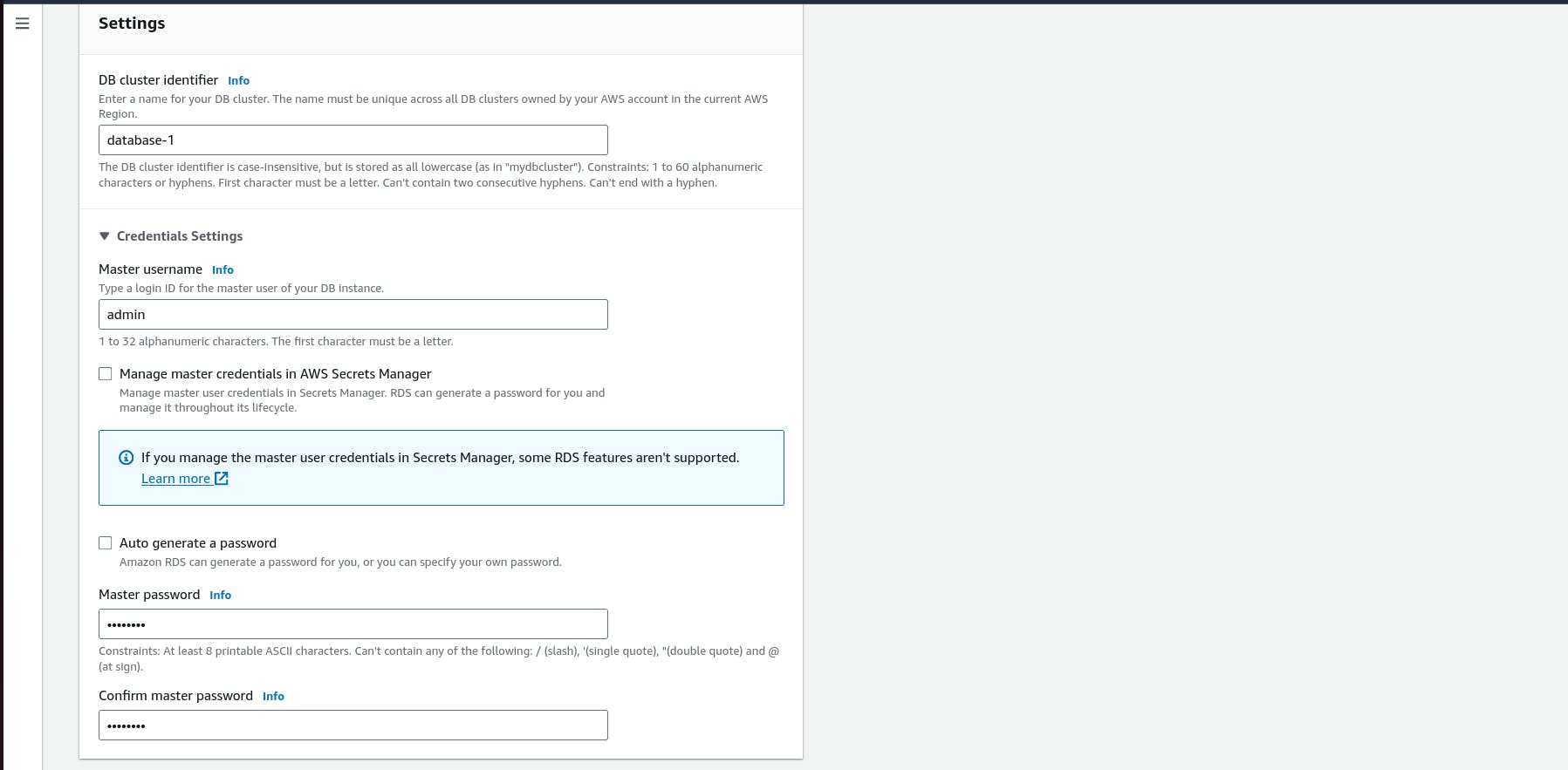
- We'll now go through several configuration steps. Start with a Standard create for this MySQL-Compatible Amazon Aurora database. Leave the rest of the defaults in the Engine options as default.

Under the Templates section choose Dev/Test since this isn't being used for production at the moment. Under Settings set a username and password of your choice and note them down since we'll be using password authentication to access our database.
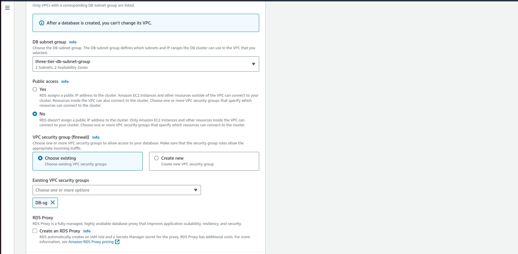
Next, under Availability and durability change the option to create an Aurora Replica or reader node in a different availability zone. Under Connectivity, set the VPC, choose the subnet group we created earlier, and select no for public access

.Set the security group we created for the database layer, make sure password authentication is selected as our authentication choice, and create the database.
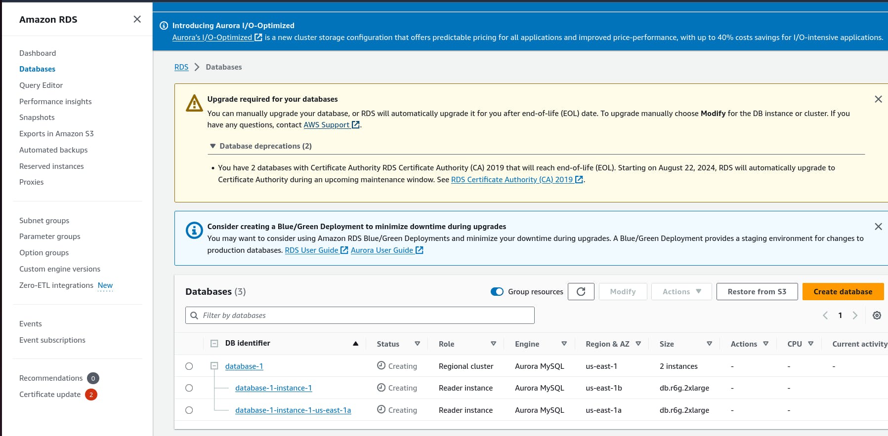
- When your database is provisioned, you should see a reader and writer instance in the database subnets of each availability zone. Note down the writer endpoint for your database for later use.
Step 9: App Instance Deployment
- Navigate to the EC2 service dashboard and click on Instances on the left hand side. Then, click Launch Instances.
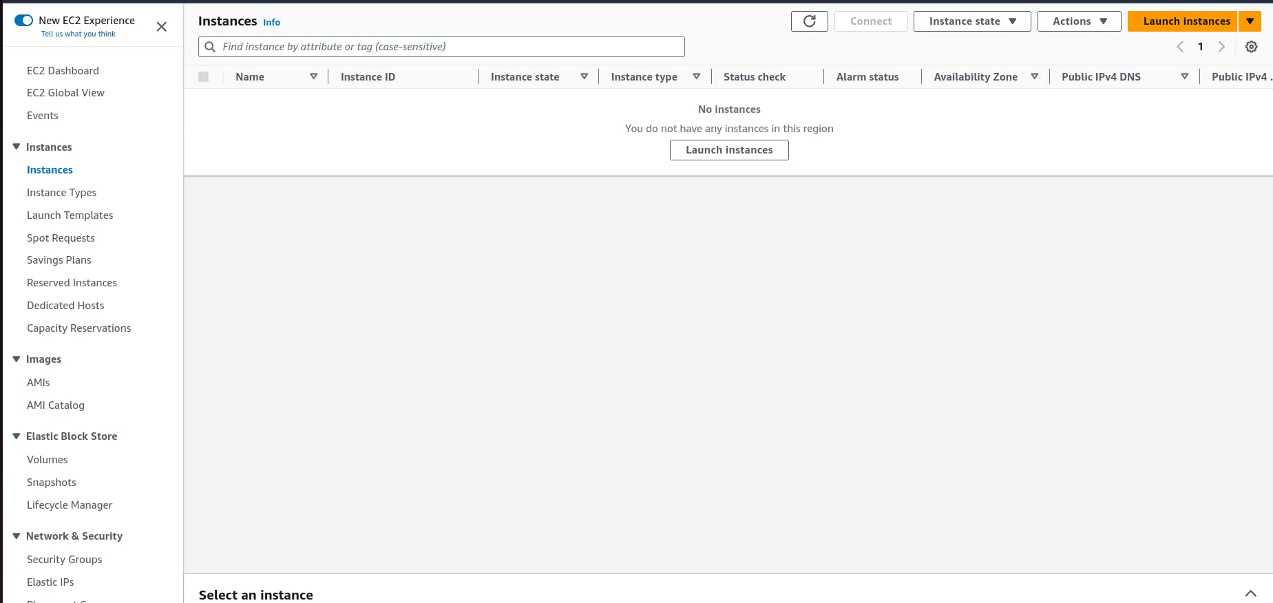
Connect to Instance
- Navigate to your list of running EC2 Instances by clicking on Instances on the left hand side of the EC2 dashboard. When the instance state is running, connect to your instance by clicking the checkmark box to the left of the instance, and click the connect button on the top right corner of the dashboard.Select the Session Manager tab, and click connect. This will open a new browser tab for you.
NOTE: If you get a message saying that you cannot connect via session manager, then check that your instances can route to your NAT gateways and verify that you gave the necessary permissions on the IAM role for the Ec2 instance.


- When you first connect to your instance like this, you will be logged in as ssm-user which is the default user. Switch to ec2-user by executing the following command in the browser terminal:
sudo -su ec2-user
- Let’s take this moment to make sure that we are able to reach the internet via our NAT gateways. If your network is configured correctly up till this point, you should be able to ping the google DNS servers:
ping 8.8.8.8
Step 10:
Configure Database
- Start by downloading the MySQL CLI:
1
sudo yum install mysql -y
- Initiate your DB connection with your Aurora RDS writer endpoint. In the following command, replace the RDS writer endpoint and the username, and then execute it in the browser terminal:
1
mysql -h CHANGE-TO-YOUR-RDS-ENDPOINT -u CHANGE-TO-USER-NAME -p
You will then be prompted to type in your password. Once you input the password and hit enter, you should now be connected to your database.
NOTE: If you cannot reach your database, check your credentials and security groups.
- Create a database called webappdb with the following command using the MySQL CLI:
1
CREATE DATABASE webappdb;
You can verify that it was created correctly with the following command:
1
SHOW DATABASES;
- Create a data table by first navigating to the database we just created:
1
USE webappdb;
Then, create the following transactions table by executing this create table command:
1
2
3
CREATE TABLE IF NOT EXISTS transactions(id INT NOT NULL
AUTO_INCREMENT, amount DECIMAL(10,2), description
VARCHAR(100), PRIMARY KEY(id));
Verify the table was created:
1
SHOW TABLES;
- Insert data into table for use/testing later:
1
INSERT INTO transactions (amount,description) VALUES ('400','groceries');
Verify that your data was added by executing the following command:
1
SELECT * FROM transactions;
- When finished, just type exit and hit enter to exit the MySQL client.
Step 11: Configure App Instance
- The first thing we will do is update our database credentials for the app tier. To do this, open the application-code/app-tier/DbConfig.js file from the github repo in your favorite text editor on your computer. You’ll see empty strings for the hostname, user, password and database. Fill this in with the credentials you configured for your database, the writer endpoint of your database as the hostname, and webappdb for the database. Save the file.
NOTE: This is NOT considered a best practice, and is done for the simplicity of the lab. Moving these credentials to a more suitable place like Secrets Manager is left as an extension for this workshop.
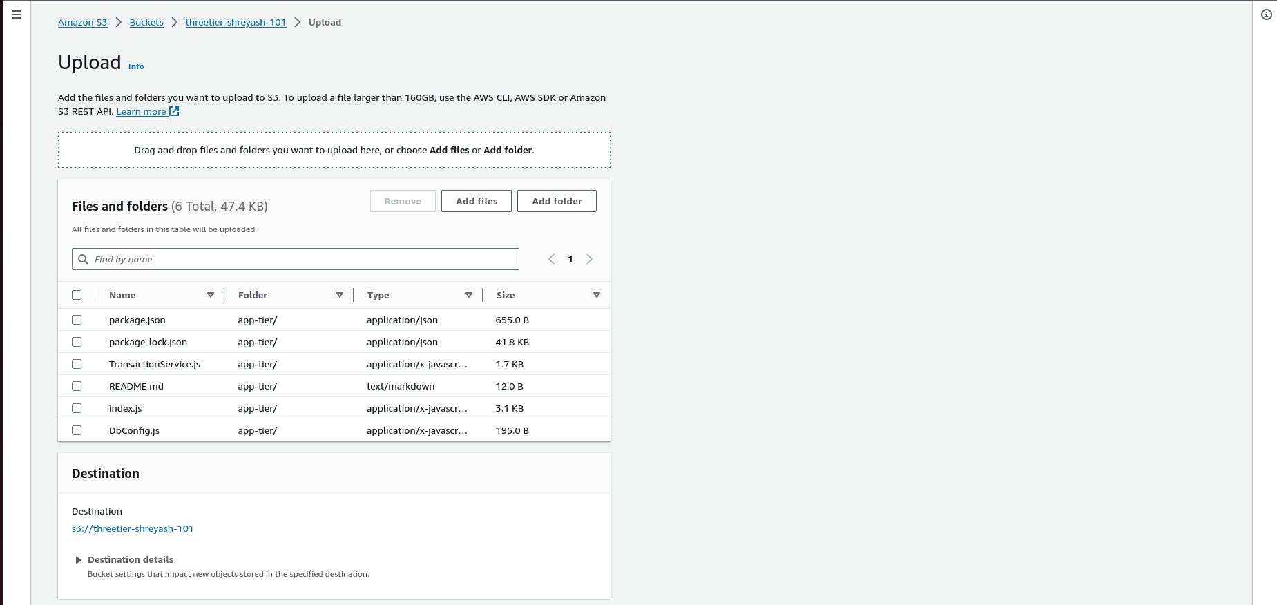
Upload the app-tier folder to the S3 bucket that you created in part 0.
Go back to your SSM session. Now we need to install all of the necessary components to run our backend application. Start by installing NVM (node version manager).
1
2
curl -o- https://raw.githubusercontent.com/nvm-sh/nvm/v0.38.0/install.sh | bash
source ~/.bashrc
- Next, install a compatible version of Node.js and make sure it's being used
1
2
nvm install 16
nvm use 16
- PM2 is a daemon process manager that will keep our node.js app running when we exit the instance or if it is rebooted. Install that as well.
1
npm install -g pm2
- Now we need to download our code from our s3 buckets onto our instance. In the command below, replace BUCKET_NAME with the name of the bucket you uploaded the app-tier folder to:
1
2
cd ~/
aws s3 cp s3://BUCKET_NAME/app-tier/ app-tier --recursive
- Navigate to the app directory, install dependencies, and start the app with pm2.
1
2
3
cd ~/app-tier
npm install
pm2 start index.js
To make sure the app is running correctly run the following:
1
pm2 list
If you see a status of online, the app is running. If you see errored, then you need to do some troubleshooting. To look at the latest errors, use this command:
1
pm2 logs
NOTE: If you’re having issues, check your configuration file for any typos, and double check that you have followed all installation commands till now.
- Right now, pm2 is just making sure our app stays running when we leave the SSM session. However, if the server is interrupted for some reason, we still want the app to start and keep running. This is also important for the AMI we will create:
1
pm2 startup
After running this you will see a message similar to this.
[PM2] To setup the Startup Script, copy/paste the following command: sudo env PATH=$PATH:/home/ec2-user/.nvm/versions/node/v16.0.0/bin /home/ec2-user/.nvm/versions/node/v16.0.0/lib/node_modules/pm2/bin/pm2 startup systemd -u ec2-user —hp /home/ec2-user
DO NOT run the above command, rather you should copy and past the command in the output you see in your own terminal. After you run it, save the current list of node processes with the following command:
1
pm2 save
Test App Tier
Now let's run a couple tests to see if our app is configured correctly and can retrieve data from the database.
To hit out health check endpoint, copy this command into your SSM terminal. This is our simple health check endpoint that tells us if the app is simply running.
1
curl http://localhost:4000/health
The response should looks like the following:
1
"This is the health check"
Next, test your database connection. You can do that by hitting the following endpoint locally:
1
curl http://localhost:4000/transaction
You should see a response containing the test data we added earlier:
1
{"result":[{"id":1,"amount":400,"description":"groceries"},{"id":2,"amount":100,"description":"class"},{"id":3,"amount":200,"description":"other groceries"},{"id":4,"amount":10,"description":"brownies"}]}
If you see both of these responses, then your networking, security, database and app configurations are correct.
- Congrats! Your app layer is fully configured and ready to go.
Step 11:
Part 4: Internal Load Balancing and Auto Scaling
In this section of the workshop we will create an Amazon Machine Image (AMI) of the app tier instance we just created, and use that to set up autoscaling with a load balancer in order to make this tier highly available.
Learning Objectives:
Create an AMI of our App Tier
Create a Launch Template
Configure Autoscaling
Deploy Internal Load Balancer
App Tier AMI
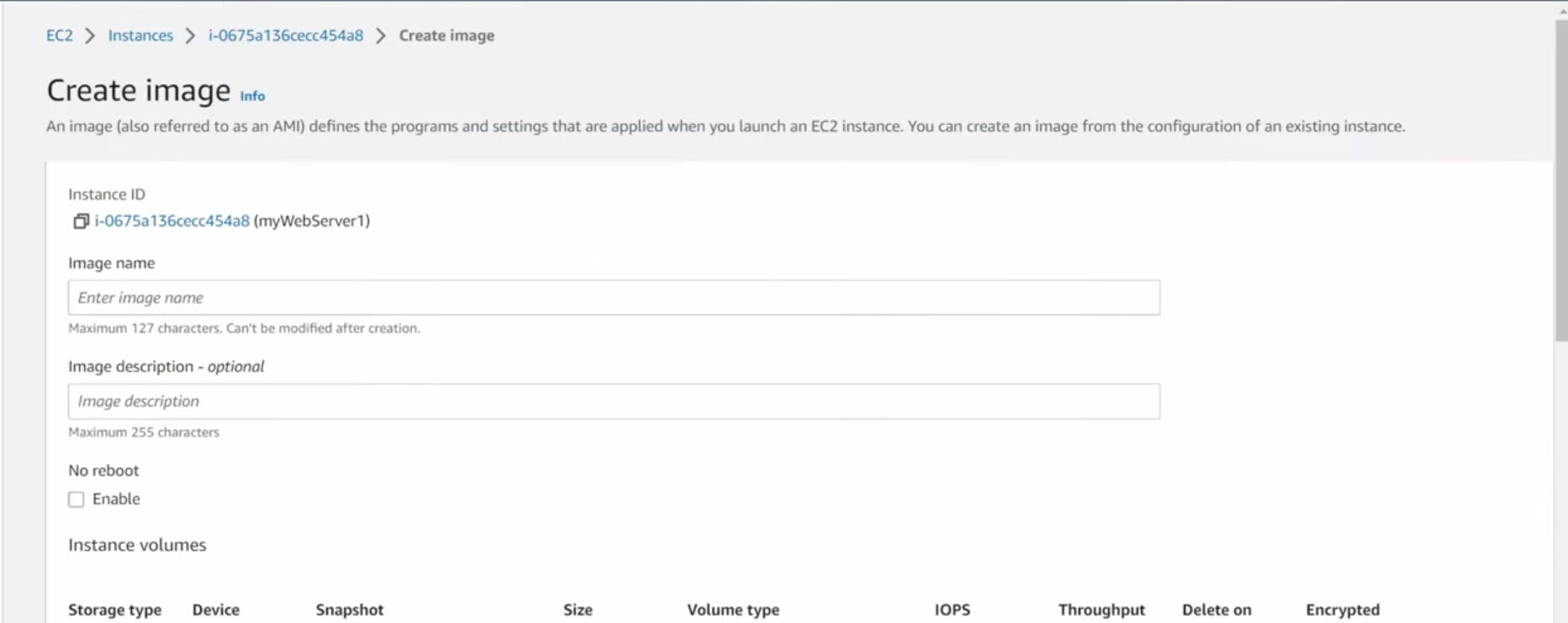
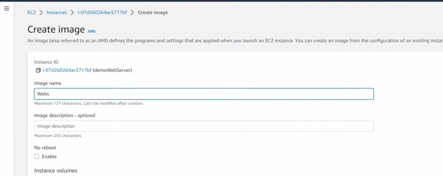
- Navigate to Instances on the left hand side of the EC2 dashboard. Select the app tier instance we created and under Actions select Image and templates. Click Create Image.

- Give the image a name and description and then click Create image. This will take a few minutes, but if you want to monitor the status of image creation you can see it by clicking AMIs under Images on the left hand navigation panel of the EC2 dashboard.
Target Group
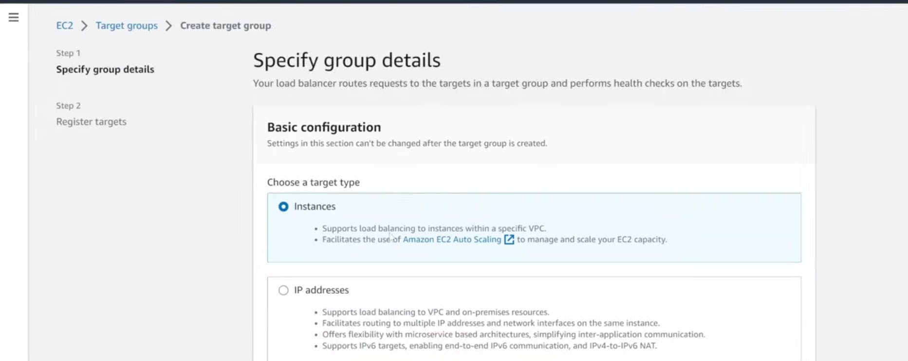
- While the AMI is being created, we can go ahead and create our target group to use with the load balancer. On the EC2 dashboard navigate to Target Groups under Load Balancing on the left hand side. Click on Create Target Group.
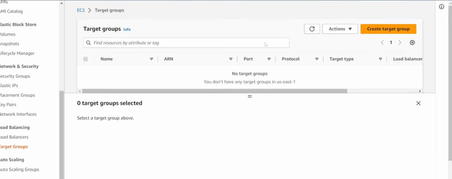
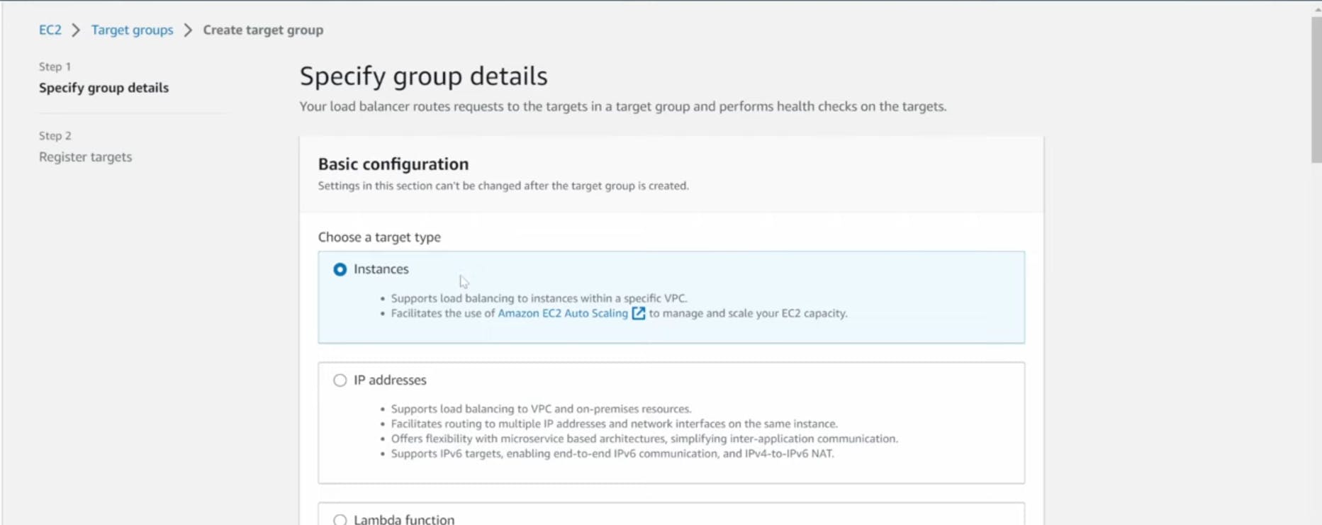
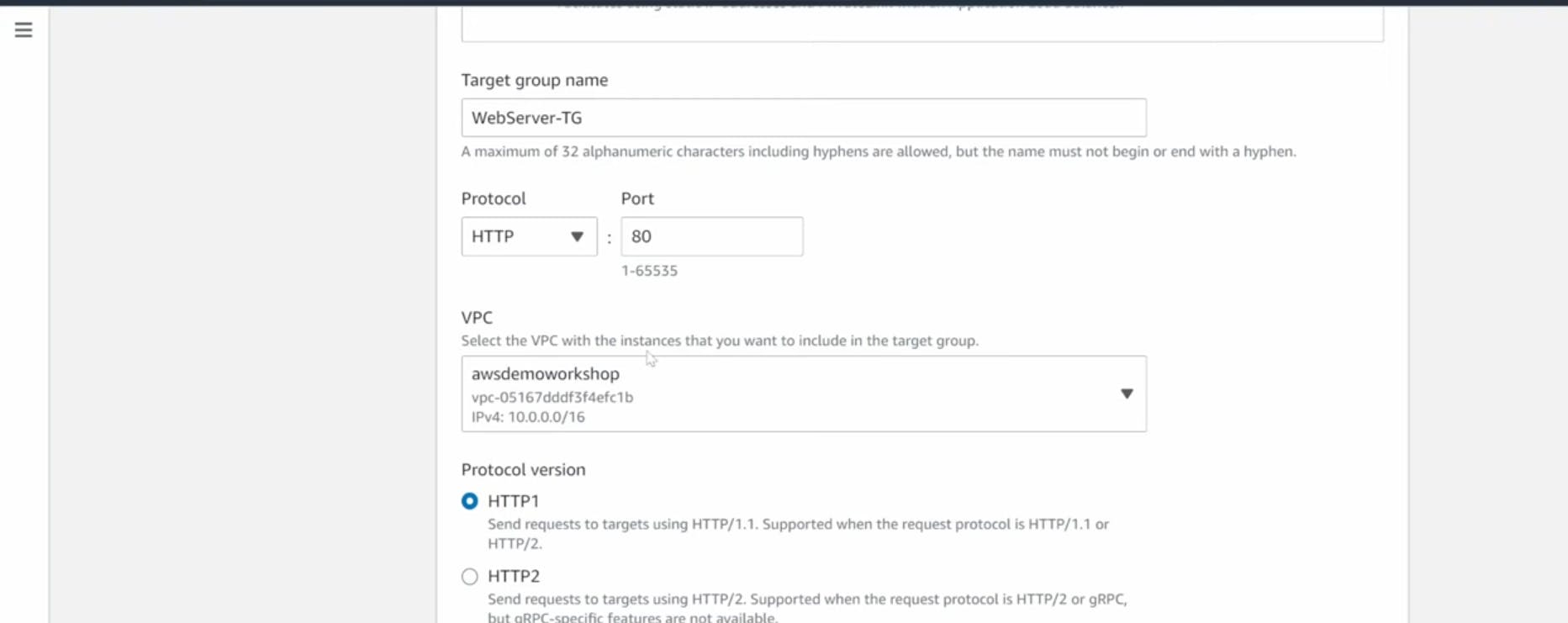
- The purpose of forming this target group is to use with our load blancer so it may balance traffic across our private app tier instances. Select Instances as the target type and give it a name.
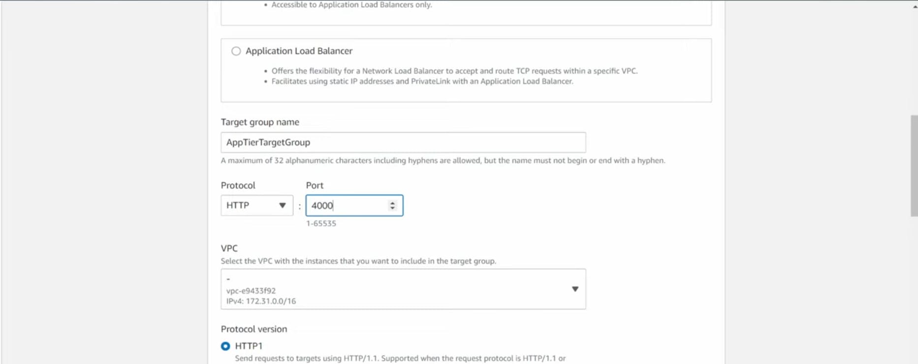
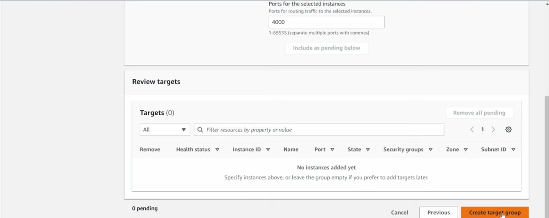
Then, set the protocol to HTTP and the port to 4000. Remember that this is the port our Node.ja app is running on. Select the VPC we've been using thus far, and then change the health check path to be /health. This is the health check endpoint of our app. Click Next.
- We are NOT going to register any targets for now, so just skip that step and create the target group.
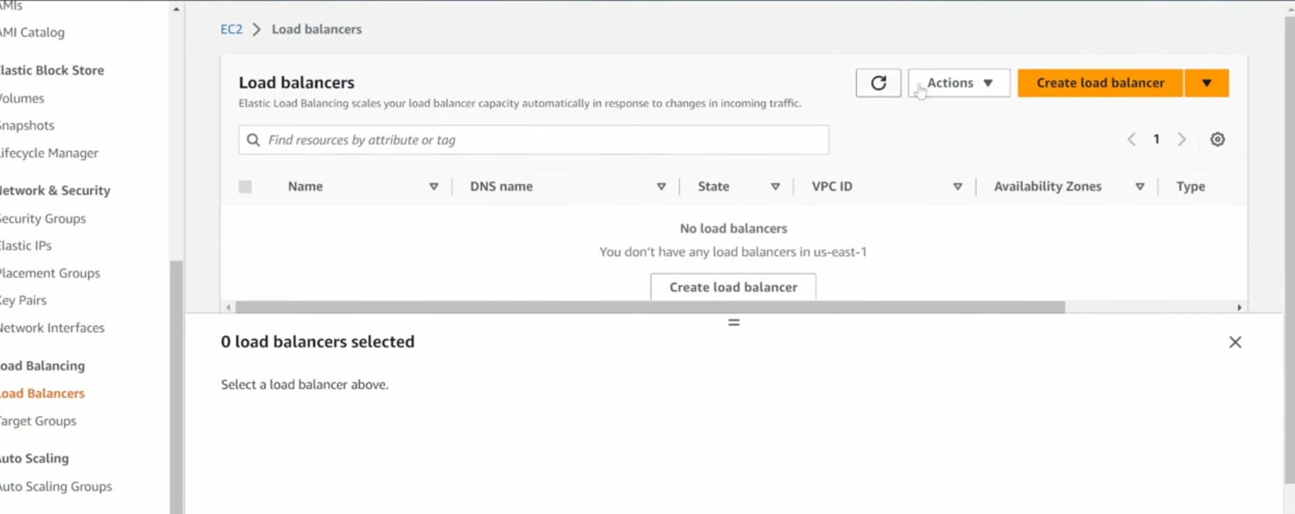
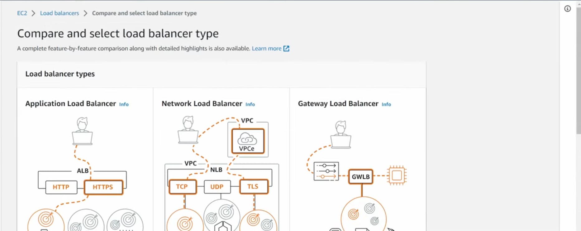
Internal Load Balancer
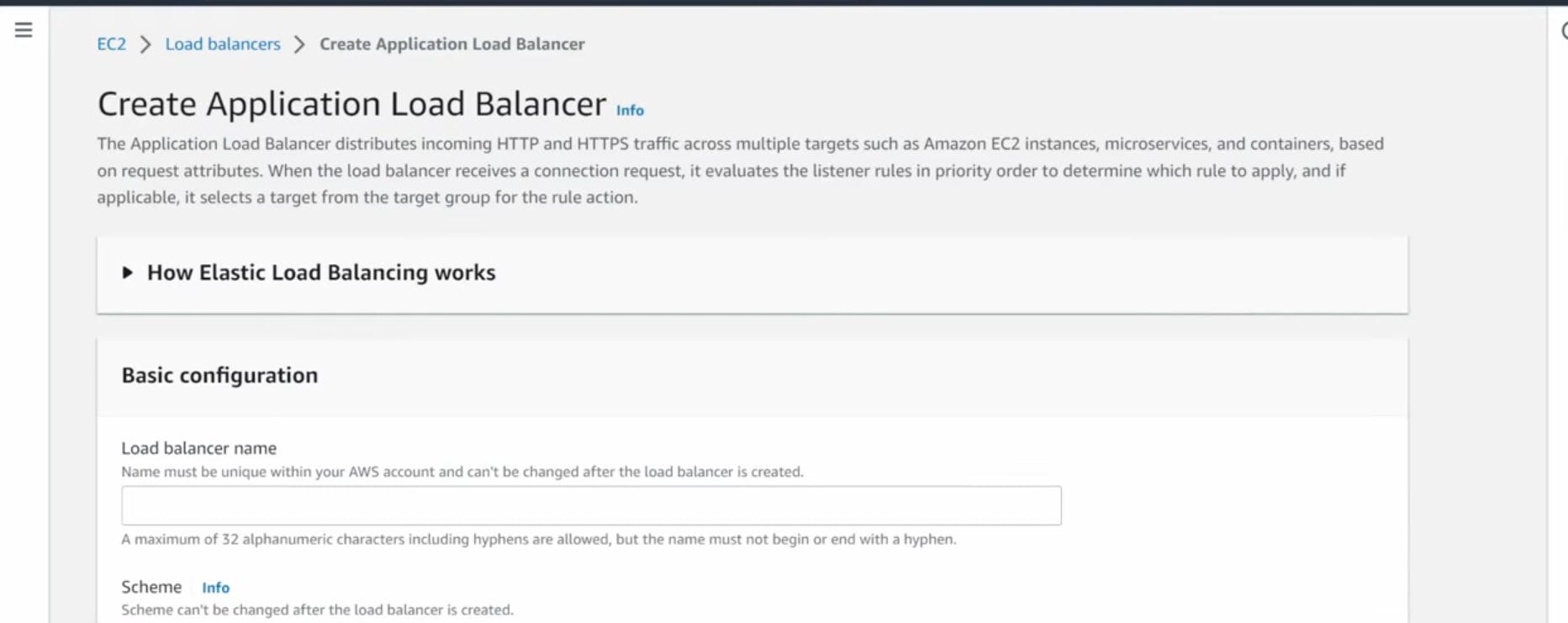
- On the left hand side of the EC2 dashboard select Load Balancers under Load Balancing and click Create Load Balancer.


Launch Template
- Before we configure Auto Scaling, we need to create a Launch template with the AMI we created earlier. On the left side of the EC2 dashboard navigate to Launch Template under Instances and click Create Launch Template.
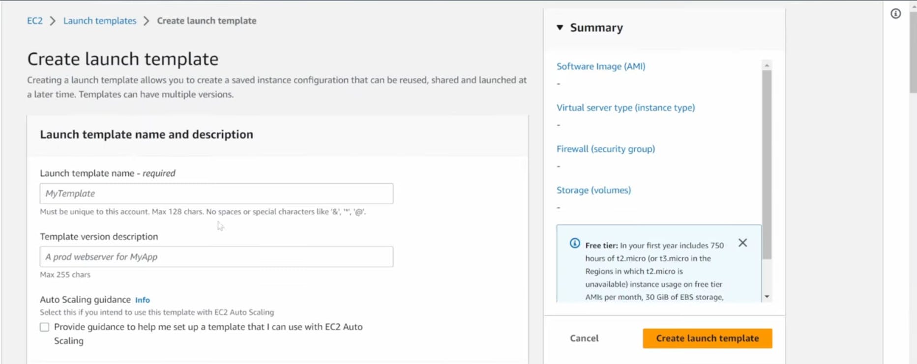
Name the Launch Template, and then under Application and OS Images include the app tier AMI you created
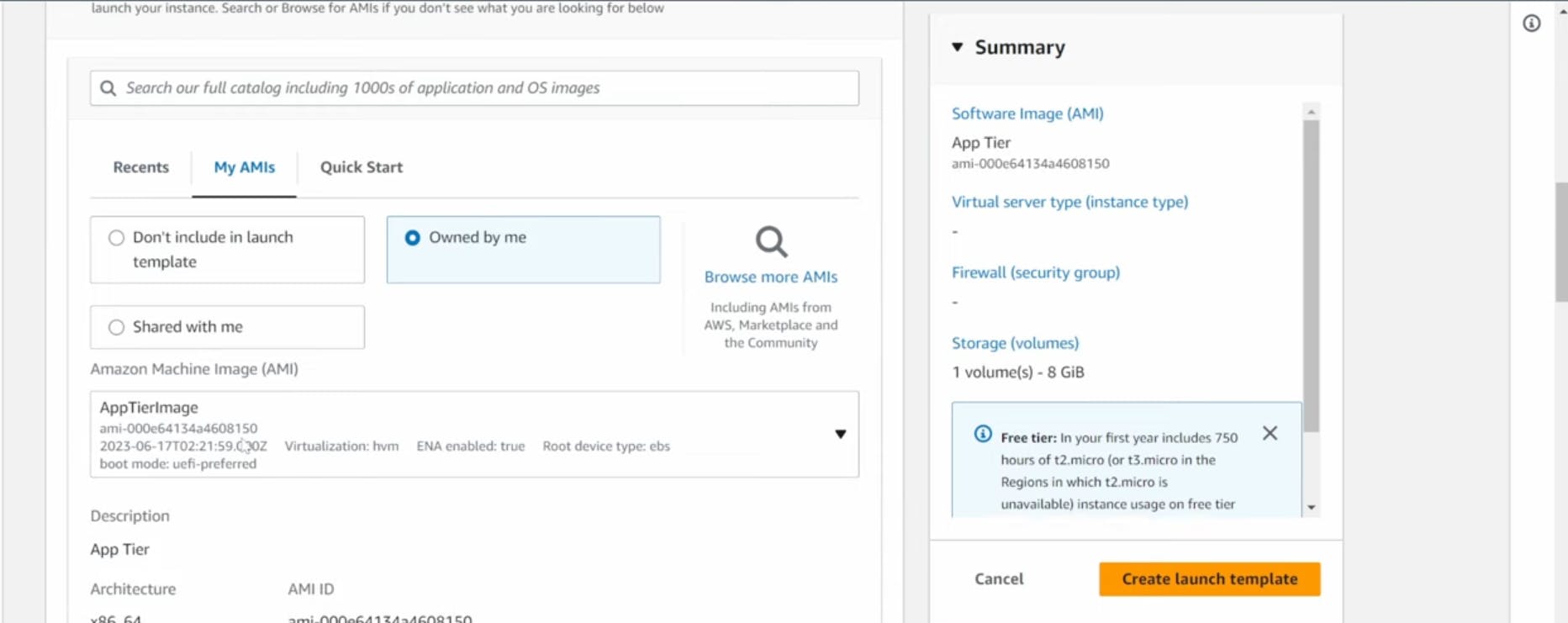
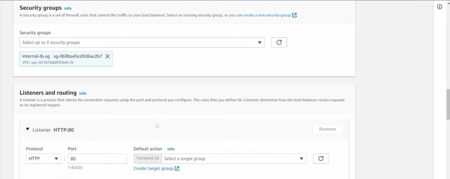
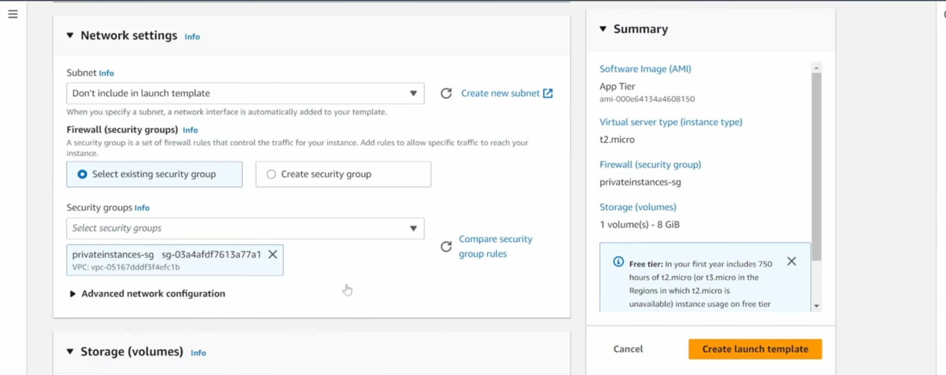
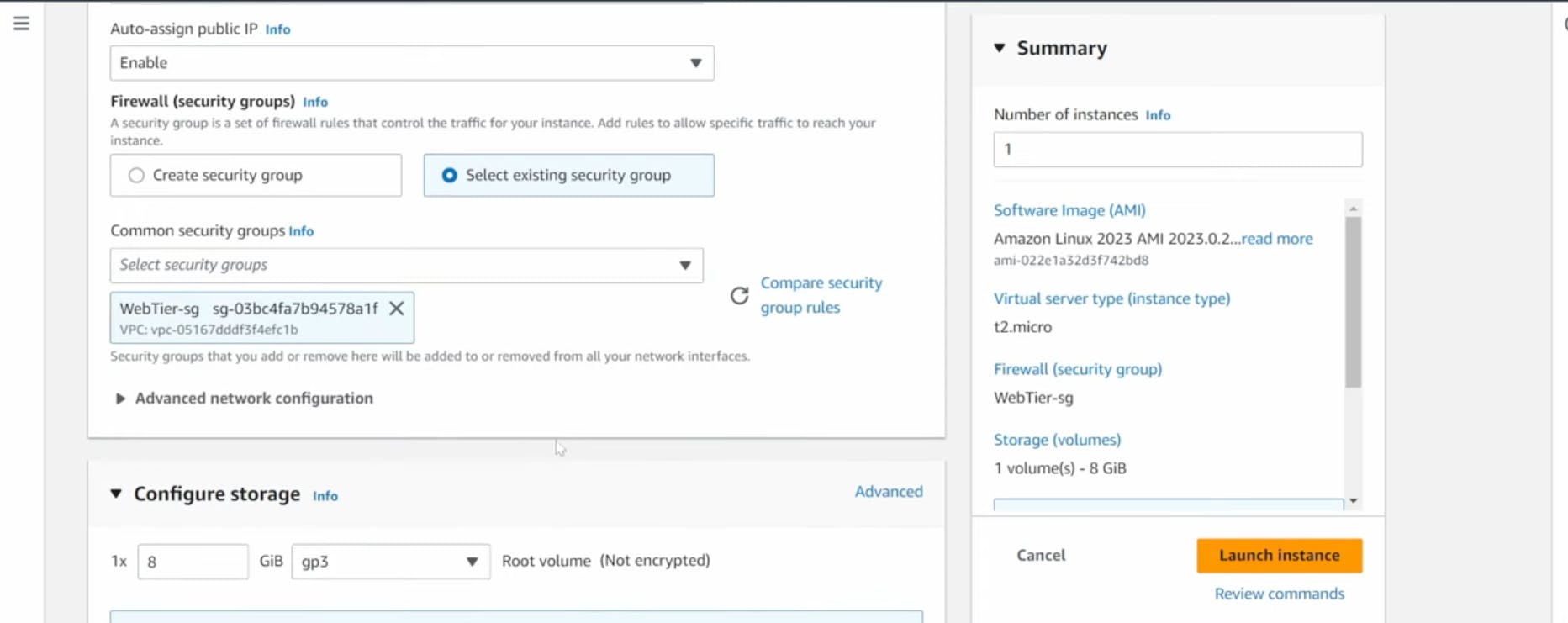
Set the correct security group for our app tier, and then under Advanced details use the same IAM instance profile we have been using for our EC2 instances.


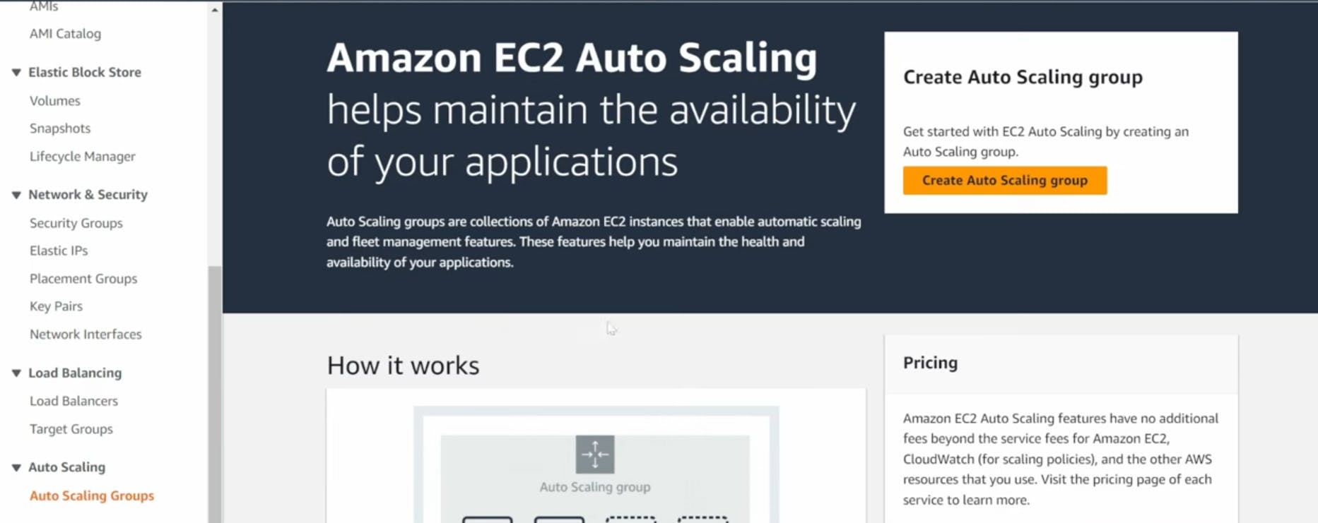
Auto Scaling
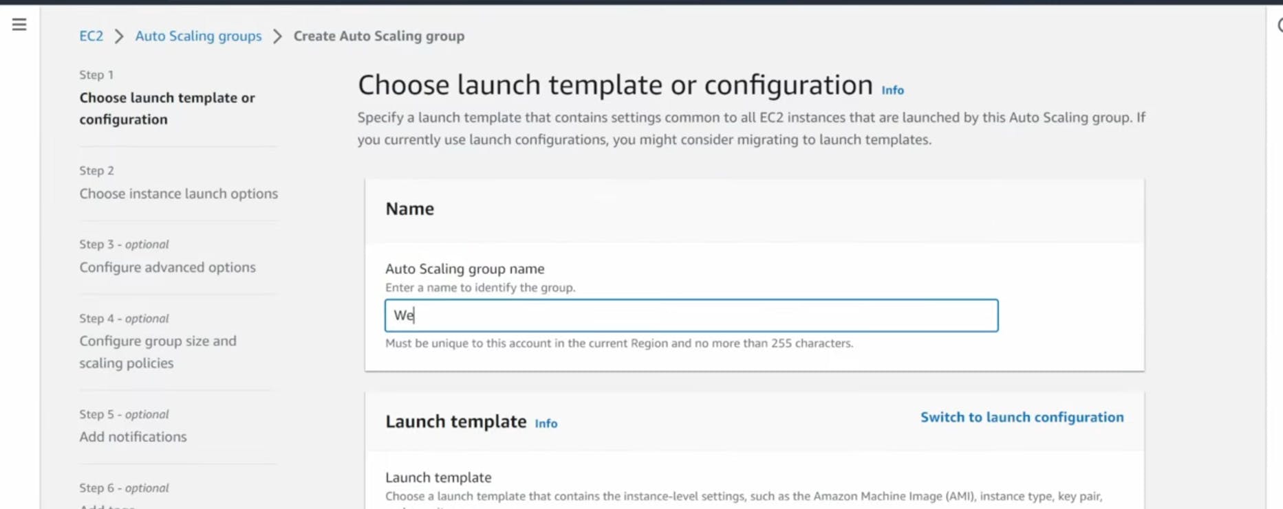
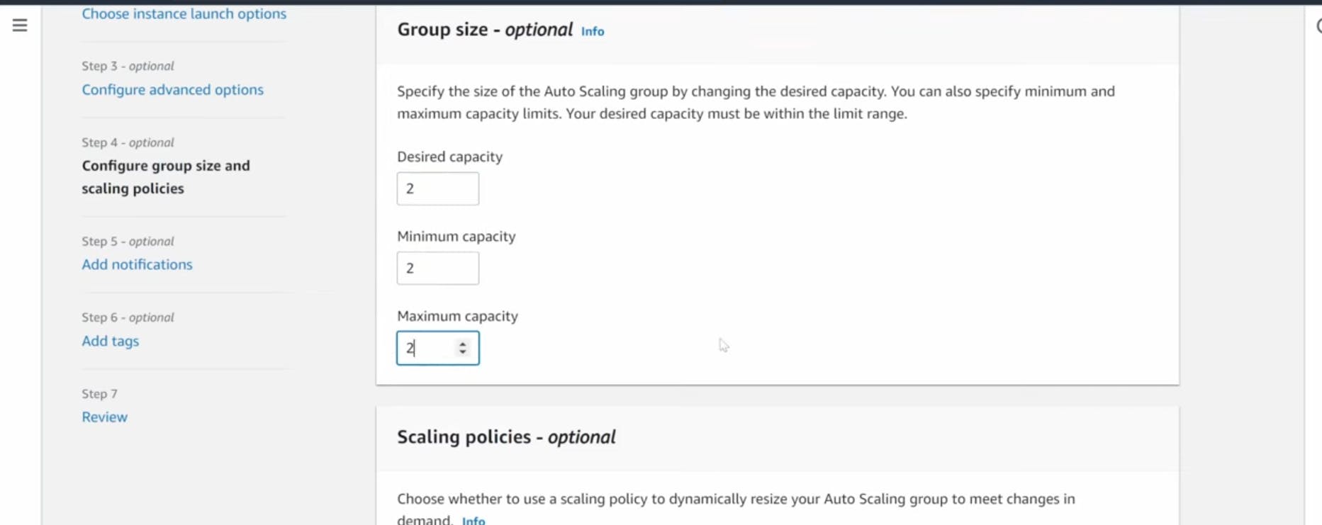
- We will now create the Auto Scaling Group for our app instances. On the left side of the EC2 dashboard navigate to Auto Scaling Groups under Auto Scaling and click Create Auto Scaling group.
- Give your Auto Scaling group a name, and then select the Launch Template we just created and click next.

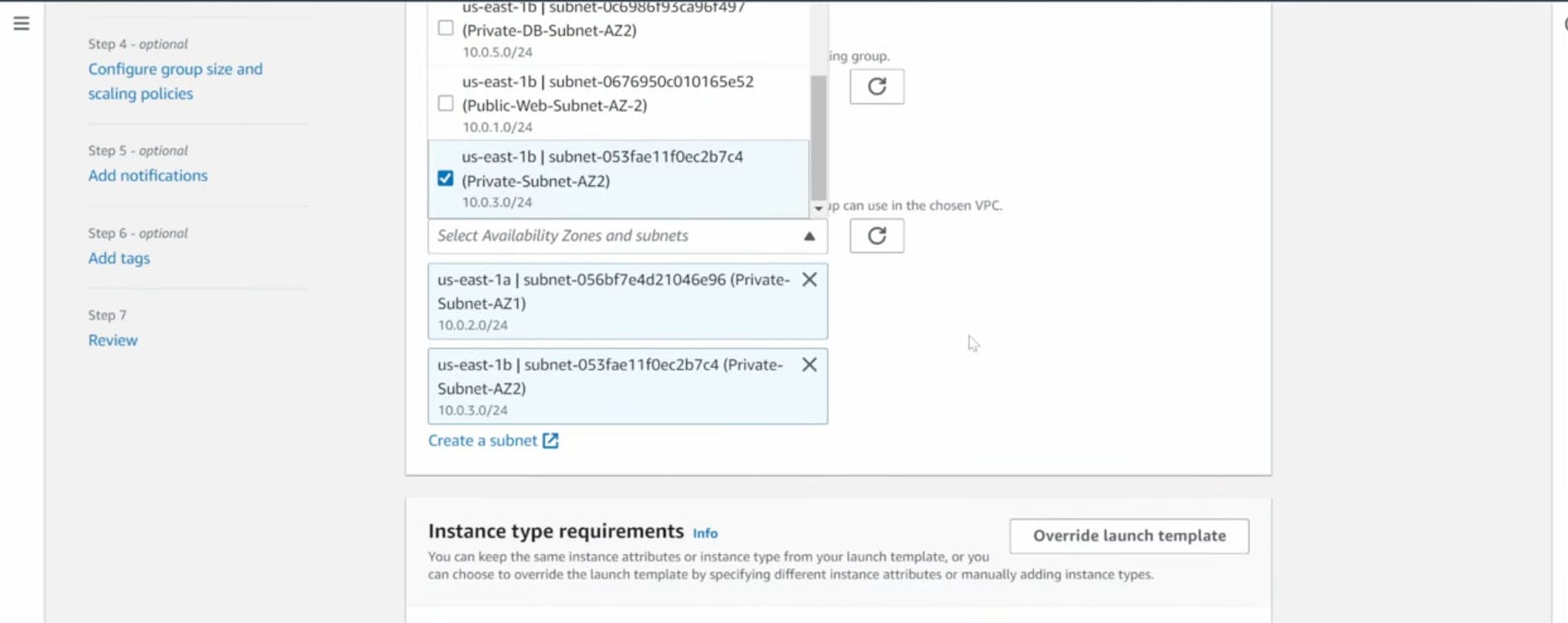
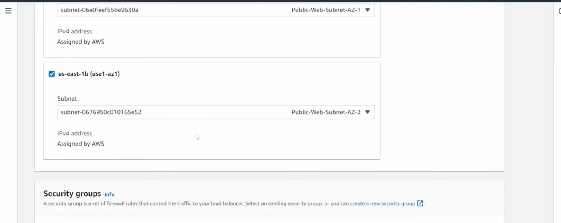
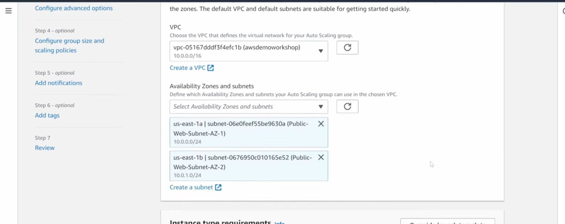
- On the Choose instance launch options page set your VPC, and the private instance subnets for the app tier and continue to step 3.
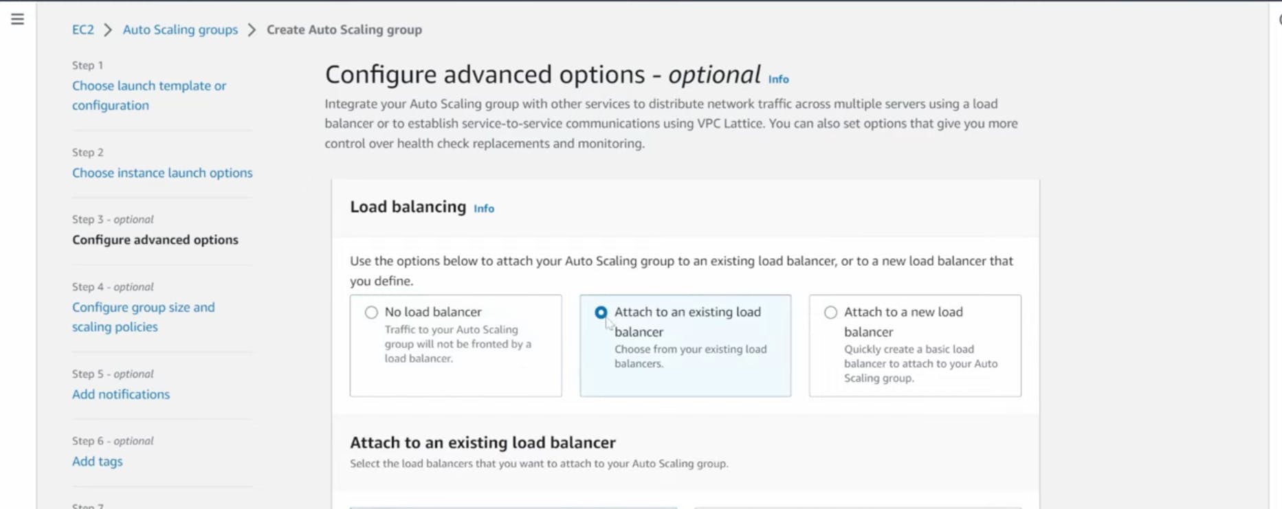
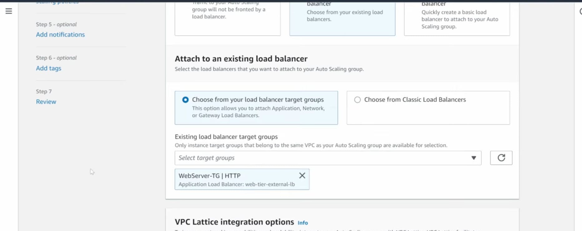
- For this next step, attach this Auto Scaling Group to the Load Balancer we just created by selecting the existing load balancer's target group from the dropdown. Then, click next.

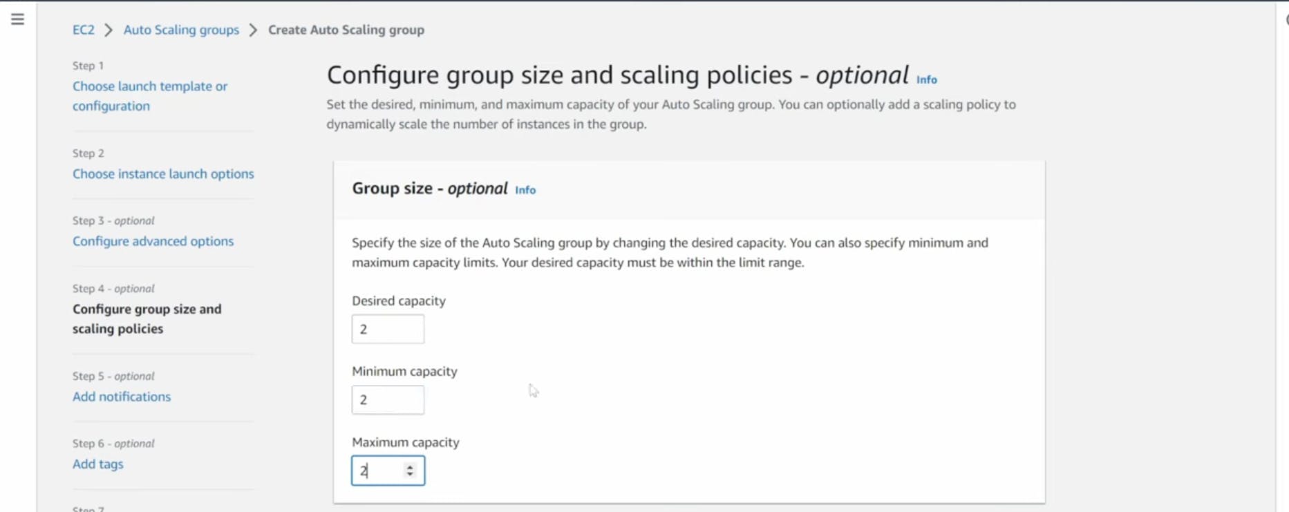
- For Configure group size and scaling policies, set desired, minimum and maximum capacity to 2. Click skip to review and then Create Auto Scaling Group.
Part 5: Web Tier Instance Deployment
In this section we will deploy an EC2 instance for the web tier and make all necessary software configurations for the NGINX web server and React.js website.
Learning Objectives
Update NGINX Configuration Files
Create Web Tier Instance
Configure Software Stack
Update Config File
Before we create and configure the web instances, open up the application-code/nginx.conf file from the repo we downloaded. Scroll down to line 58 and replace [INTERNAL-LOADBALANCER-DNS] with your internal load balancer’s DNS entry. You can find this by navigating to your internal load balancer's details page.

Then, upload this file and the application-code/web-tier folder to the s3 bucket you created for this lab.
Web Instance Deployment
- Follow the same instance creation instructions we used for the App Tier instance in Part 3: App Tier Instance Deployment, with the exception of the subnet. We will be provisioning this instance in one of our public subnets. Make sure to select the correct network components, security group, and IAM role. This time, auto-assign a public ip on the Configure Instance Details page. Remember to tag the instance with a name so we can identify it more easily.


Connect to Instance
- Follow the same steps you used to connect to the app instance and change the user to ec2-user. Test connectivity here via ping as well since this instance should have internet connectivity:
1
2
sudo -su ec2-user
ping 8.8.8.8
Note: If you don't see a transfer of packets then you'll need to verify your route tables attached to the subnet that your instance is deployed in.
Configure Web Instance
- We now need to install all of the necessary components needed to run our front-end application. Again, start by installing NVM and node :
1
2
3
4
curl -o- https://raw.githubusercontent.com/nvm-sh/nvm/v0.38.0/install.sh | bash
source ~/.bashrc
nvm install 16
nvm use 16
- Now we need to download our web tier code from our s3 bucket:
cd ~/
aws s3 cp s3://BUCKET_NAME/web-tier/ web-tier --recursive
Navigate to the web-layer folder and create the build folder for the react app so we can serve our code:
1
2
3
cd ~/web-tier
npm install
npm run build
- NGINX can be used for different use cases like load balancing, content caching etc, but we will be using it as a web server that we will configure to serve our application on port 80, as well as help direct our API calls to the internal load balancer.
1
sudo amazon-linux-extras install nginx1 -y
- We will now have to configure NGINX. Navigate to the Nginx configuration file with the following commands and list the files in the directory:
1
2
cd /etc/nginx
ls
You should see an nginx.conf file. We’re going to delete this file and use the one we uploaded to s3. Replace the bucket name in the command below with the one you created for this workshop:
1
2
sudo rm nginx.conf
sudo aws s3 cp s3://BUCKET_NAME/nginx.conf .
Then, restart Nginx with the following command:
1
sudo service nginx restart
To make sure Nginx has permission to access our files execute this command:
1
chmod -R 755 /home/ec2-user
And then to make sure the service starts on boot, run this command:
1
sudo chkconfig nginx on
- Now when you plug in the public IP of your web tier instance, you should see your website, which you can find on the Instance details page on the EC2 dashboard. If you have the database connected and working correctly, then you will also see the database working. You’ll be able to add data. Careful with the delete button, that will clear all the entries in your database.


Part 6: External Load Balancer and Auto Scaling
In this section of the workshop we will create an Amazon Machine Image (AMI) of the web tier instance we just created, and use that to set up autoscaling with an external facing load balancer in order to make this tier highly available.
Learning Objectives:
Create an AMI of our Web Tier
Create a Launch Template
Configure Auto Scaling
Deploy External Load BalanceWeb Tier AMI
- Navigate to Instances on the left hand side of the EC2 dashboard. Select the web tier instance we created and under Actions select Image and templates. Click Create Image.
Target Group
- While the AMI is being created, we can go ahead and create our target group to use with the load balancer. On the EC2 dashboard navigate to Target Groups under Load Balancing on the left hand side. Click on Create Target Group.
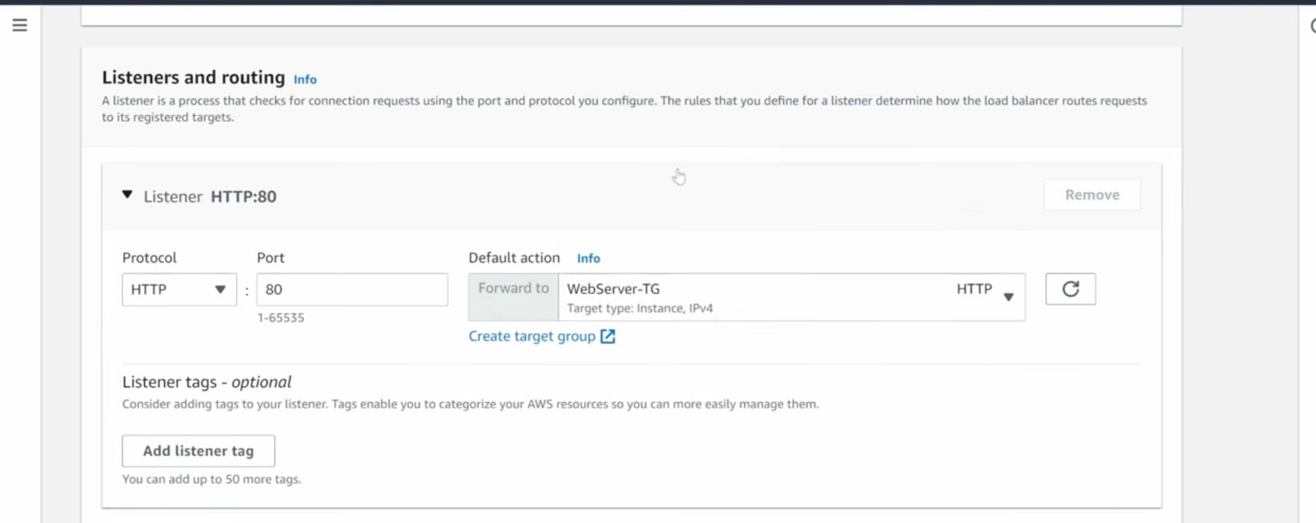
Internet Facing Load Balancer
- On the left hand side of the EC2 dashboard select Load Balancers under Load Balancing and click Create Load Balancer.

Launch Template
- Before we configure Auto Scaling, we need to create a Launch template with the AMI we created earlier. On the left side of the EC2 dashboard navigate to Launch Template under Instances and click Create Launch Template.


Auto Scaling
- We will now create the Auto Scaling Group for our web instances. On the left side of the EC2 dashboard navigate to Auto Scaling Groups under Auto Scaling and click Create Auto Scaling group.


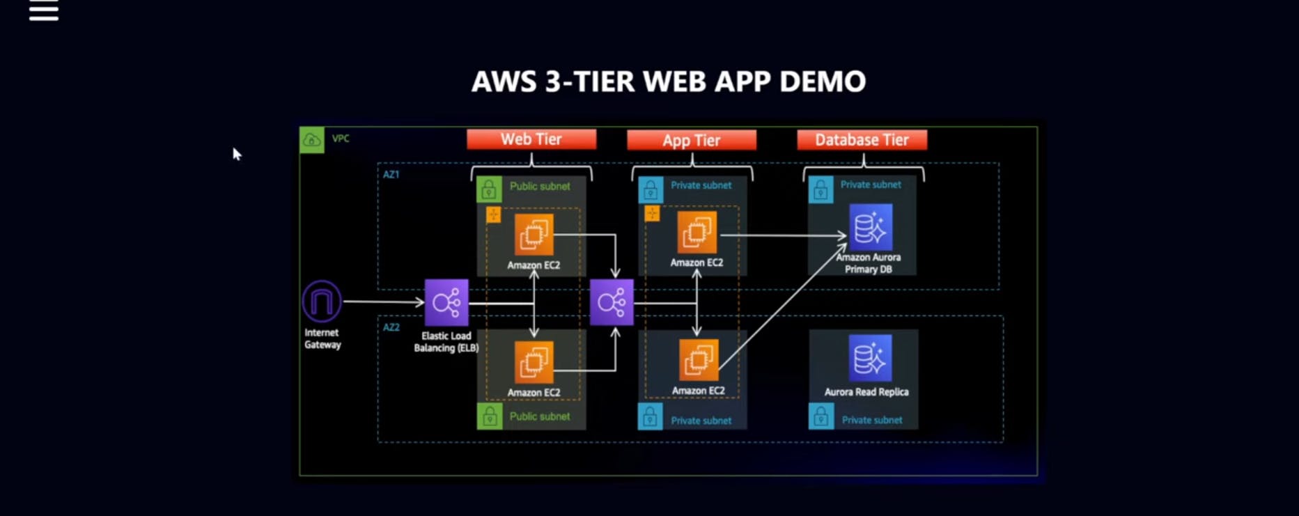
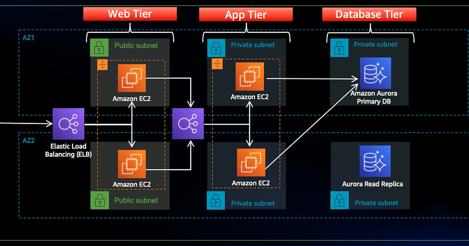
Certainly, let's break down the deployment of a three-tier architecture on AWS into more detailed steps, including the use of subnets, public and private subnets, and the associated AWS services. We'll assume that you want to deploy this architecture in a Virtual Private Cloud (VPC) for network isolation and security. Here's a step-by-step guide:
Step 1: AWS Account Setup and Region Selection:
Sign up for an AWS account if you don't have one.
Choose the AWS region where you want to deploy your resources. Different regions may offer different availability zones and services.
Step 2: Create a Virtual Private Cloud (VPC):
Navigate to the AWS VPC service.
Create a new VPC. Specify an IP address range (CIDR block) for your VPC, e.g.,
10.0.0.0/16.
Step 3: Create Subnets:
Within your VPC, create multiple subnets. Here's a common setup:
Public Subnets: These subnets allow resources within them to have direct internet access.
- Create at least two public subnets in different availability zones (e.g.,
10.0.1.0/24and10.0.2.0/24).
- Create at least two public subnets in different availability zones (e.g.,
Private Subnets: These subnets do not have direct internet access.
- Create at least two private subnets in different availability zones (e.g.,
10.0.3.0/24and10.0.4.0/24).
- Create at least two private subnets in different availability zones (e.g.,
Step 4: Configure Route Tables:
Create route tables for public and private subnets.
Associate public subnets with a route table that has a route to the internet via an Internet Gateway (IGW).
Associate private subnets with a route table that routes traffic through a Network Address Translation (NAT) Gateway or NAT instance in the public subnets.
Step 5: Set Up the Presentation Layer (Frontend):
Create or upload your frontend code to an Amazon S3 bucket.
Configure the S3 bucket to act as a static website host.
Use Amazon CloudFront for content delivery and SSL/TLS support if needed.
Place the frontend in the public subnet(s).
Step 6: Set Up the Application Layer (Backend):
Deploy your backend application using AWS Elastic Beanstalk (for server-based applications) or AWS Lambda (for serverless applications).
Configure the backend instances or Lambda functions to run in the private subnet(s).
If you use AWS Elastic Beanstalk, ensure that it's behind an Application Load Balancer (ALB) for load balancing and routing.
Step 7: Set Up the Data Layer (Database):
Choose an appropriate database solution (e.g., Amazon RDS, DynamoDB, or Aurora).
Configure security groups to control inbound and outbound database traffic.
Place the database instances in the private subnet(s).
Ensure data encryption, backup, and high availability based on the chosen database service.
Step 8: Security and IAM Roles:
Create IAM roles for services that need to access other AWS resources securely.
Apply security groups to control inbound and outbound traffic to instances.
Use Network ACLs (if necessary) to control traffic at the subnet level.
Step 9: Elastic Load Balancer (Optional):
If your application requires high availability and load balancing, set up an Elastic Load Balancer (ELB) in the public subnet(s).
Configure the ELB to distribute traffic to backend instances.
Step 10: DNS and Route 53 (Optional):
Set up DNS records using Amazon Route 53 to map your custom domain to your application endpoints.
Configure Route 53 health checks for monitoring the availability of your services.
Step 11: Monitoring and Logging:
Implement monitoring and logging using AWS CloudWatch, AWS CloudTrail, and AWS X-Ray.
Set up alarms and notifications for key metrics and events.
Step 12: Testing and Quality Assurance:
Thoroughly test your application to ensure that it functions correctly within the architecture.
Conduct load testing to assess performance and scalability.
Step 13: Backup and Disaster Recovery (Optional):
Implement backup and disaster recovery plans for data and infrastructure.
Configure automated snapshots and backups for databases.
Step 14: Scaling and Optimization:
Use Auto Scaling groups (for EC2 instances) or serverless scaling (for Lambda) to handle increased load.
Continuously optimize AWS resources to control costs.
Step 15: Documentation and Training:
Document your architecture, deployment procedures, and configurations.
Train your team on managing and maintaining the AWS resources.
Step 16: Deployment and Maintenance:
Deploy your application to the production environment.
Set up automated deployment pipelines using AWS CodePipeline or other CI/CD tools.
Regularly update and maintain your application and infrastructure.
This step-by-step guide provides a detailed overview of deploying a three-tier architecture on AWS, including the use of subnets (public and private) to create network isolation and security. Remember that the specific services and configurations may vary depending on your application's requirements, and it's crucial to follow AWS best practices for security, scalability, and reliability throughout the process.
Certainly! Let's focus on the presentation layer of a 3-tier architecture and how components like subnets, security groups, Elastic Load Balancers (ELBs), and Auto Scaling groups are typically used in this layer:
Presentation Layer:
Subnets:
In the presentation layer, subnets are used to group together instances that handle user interactions and client-side components, such as web servers or application servers.
Typically, public subnets are used in this layer because they allow instances to have direct access to the internet. This is important for serving web applications to users.
Security Groups:
Security groups are applied to instances in the presentation layer to control inbound and outbound traffic.
Inbound security group rules are configured to allow specific types of traffic, such as HTTP (port 80) and HTTPS (port 443), from specific sources (e.g., the internet) to reach the instances.
Outbound security group rules may be configured to allow these instances to communicate with other layers or external services, such as a database server.
Elastic Load Balancer (ELB):
ELB is a crucial component of the presentation layer. It distributes incoming user requests and traffic across multiple instances (usually web servers) to ensure high availability and scalability.
ELB can be placed in a public subnet, acting as the entry point for user requests, and can distribute traffic to instances in private subnets.
Auto Scaling Group:
Auto Scaling groups are used in the presentation layer to automatically add or remove instances based on demand.
When the load on web servers increases, new instances are launched to handle the load. When the load decreases, excess instances are terminated to save costs.
Auto Scaling groups work seamlessly with ELB to ensure that new instances are automatically registered and available for incoming traffic.
Example Scenario:
Let's say you are hosting a web application on AWS:
Your web servers (part of the presentation layer) are placed in public subnets to allow direct internet access.
Security groups for the web servers restrict inbound traffic to only HTTP (port 80) and HTTPS (port 443) from the internet.
You configure an Application Load Balancer (ALB) in a public subnet. The ALB distributes incoming user requests to the web servers in the private subnets.
You create an Auto Scaling group for the web servers to handle varying levels of traffic. As user demand increases, the Auto Scaling group launches additional web server instances and registers them with the ALB.
In this scenario, subnets, security groups, Elastic Load Balancers, and Auto Scaling groups in the presentation layer work together to ensure the web application is highly available, scalable, and secure, while also managing the network configuration for user interactions.
Certainly! Let's discuss how components like subnets, security groups, Elastic Load Balancers (ELBs), and Auto Scaling groups are typically used in the application layer of a 3-tier architecture:
Application Layer:
Subnets:
In the application layer, subnets are used to host the application servers or microservices. These application servers are responsible for processing business logic and application-specific functionality.
It's common to place application servers in private subnets to enhance security by isolating them from direct internet access.
Security Groups:
Security groups are applied to instances in the application layer to control inbound and outbound traffic.
Inbound security group rules are configured to allow traffic from specific sources (e.g., the presentation layer) to reach the application servers on the required ports.
Outbound security group rules may be configured to allow application servers to communicate with other layers, such as the data layer (e.g., a database server) or external services.
Elastic Load Balancer (ELB):
ELB can be used in the application layer to distribute incoming requests among multiple application server instances for load balancing and high availability.
Application Load Balancers (ALBs) are commonly used in this layer because they can route requests based on content, such as HTTP headers or URL paths, to different application servers or microservices.
Auto Scaling Group:
Auto Scaling groups can also be utilized in the application layer to manage the number of application server instances based on demand.
As the workload increases, new application server instances are automatically launched and added to the load balancer pool. Conversely, during periods of lower demand, excess instances can be terminated to save costs.
Example Scenario:
Let's consider an e-commerce website as an example:
The application layer hosts the e-commerce application servers that handle tasks like processing customer orders, managing user profiles, and inventory management.
These application servers are placed in private subnets to prevent direct access from the internet, enhancing security.
Security groups are configured to allow inbound traffic from the presentation layer (e.g., web servers) on specific ports relevant to the application's APIs and services.
An Application Load Balancer (ALB) is set up in the private subnet to distribute incoming API requests among the application server instances.
An Auto Scaling group is associated with the application servers to automatically adjust the number of instances based on the number of incoming requests or load, ensuring the application remains responsive and available.
In this application layer scenario, subnets, security groups, Elastic Load Balancers (specifically ALBs), and Auto Scaling groups collaborate to ensure that the application is highly available, scalable, and secure, while also managing the network configuration for application-specific logic and processing.
Certainly! Let's explore how components like subnets, security groups, Elastic Load Balancers (ELBs), and Auto Scaling groups are typically used in the data layer of a 3-tier architecture:
Data Layer:
Subnets:
In the data layer, subnets are used to host databases, data storage systems, and other data-related resources.
For enhanced security, it's common to place data layer components in private subnets that are isolated from direct internet access. This isolation helps protect sensitive data.
Security Groups:
Security groups play a critical role in controlling access to the data layer. They are applied to database instances, data storage servers, and other data-related resources.
Inbound security group rules are configured to allow specific application servers or application components (e.g., those in the application layer) to access the data layer on the necessary ports.
Outbound security group rules can be used to specify which outbound traffic is allowed from the data layer, such as allowing outbound traffic to specific services or IP ranges.
Elastic Load Balancer (ELB):
In some cases, you might use an ELB, such as a Network Load Balancer (NLB), to distribute read-heavy database queries or traffic across multiple database instances.
An NLB can be placed in front of read replicas or database clusters to ensure that read queries are distributed efficiently.
Auto Scaling Group:
While Auto Scaling is commonly associated with compute instances, it can also be relevant in the data layer. For example, if you have read replicas in a database cluster, you can configure Auto Scaling for these replicas to handle increased read workloads.
Auto Scaling ensures that the data layer can automatically adjust its capacity based on demand, providing scalability and reliability.
Example Scenario:
Consider a scenario for an e-commerce application:
The data layer hosts a relational database that stores customer information, order history, and product catalog data.
Database instances are placed in private subnets to restrict direct access from the internet.
Security groups are configured to allow inbound traffic only from application servers in the application layer, on database-specific ports (e.g., port 3306 for MySQL).
In some cases, an NLB might be used to distribute read queries across read replicas, ensuring efficient use of database resources.
Auto Scaling for read replicas ensures that the data layer can automatically adjust to handle varying read workloads, providing performance and scalability.
In this data layer scenario, subnets, security groups, Elastic Load Balancers (if applicable), and Auto Scaling groups work together to ensure the security, availability, and scalability of the data storage and database resources while managing network configurations for data access and storage.